Swiveling rebar fastener

a rebar and swivel technology, applied in the direction of rod connections, couplings, manufacturing tools, etc., can solve the problems of steel wire, wire may rust an appreciable amount, and reduce the strength of the wire,

Inactive Publication Date: 2005-10-06
JIFFY CLIP
View PDF15 Cites 68 Cited by
  • Summary
  • Abstract
  • Description
  • Claims
  • Application Information

AI Technical Summary

Benefits of technology

[0011] One embodiment of the present invention comprises a rebar fastener. The fastener includes a first clamp piece that has a first clamp that is adapted to be secured around a first piece of concrete rebar and a unitarily formed opening. The fastener also includes a second clamp piece that has a second clamp that i

Problems solved by technology

There are, however, several disadvantages to using steel wire.
First, the wire is subject to rust especially when utilized in moist environments.
This can be problematic in several ways.
If there is a significant period of time between the fabrication of the rebar grid and the pouring of the concrete over the grid, the wire may rust an appreciable amount significantly reducing its strength.
Further, any rust on the wire prior to pouring and any rust that forms after pouring while in contact with moisture can leach out of the concrete and cause unsightly discoloration and staining of the resulting structure.
While coating the steel wire helps mitigate the problem rust, the coatings are often fragile and can flake off during the application of the wire.
Another problem of using steel wire is that the wire can be significantly weakened as it is plastically deformed while being twisted in place.
The extent to which a wire has been weakened may not be readily evidence to an installer and accordingly, the weakened wire can break during the pouring of the concrete.
Conversely, if an installer fails to tighten the wire sufficiently for fear of weakening the wire, the associated rebar pieces could move unacceptably during the pouring of the concrete.
Fabricating the rebar grid using wire can be extremely labor intensive as each wire at each intersection of the rebar pieces in the grid must be manually wrapped around the intersection and twisted to hold the rebar in place.
Often the amount of space between the various pieces of rebar in a grid is not significant making the process more difficult and time-consuming for an installer.
The repetitive action of twisting the steel wires can cause or aggravate carpal tunnel syndrome in the installer as well.
There are several issues related t

Method used


Image

  • Swiveling rebar fastener
  • Swiveling rebar fastener
  • Swiveling rebar fastener

Examples


Embodiment Construction

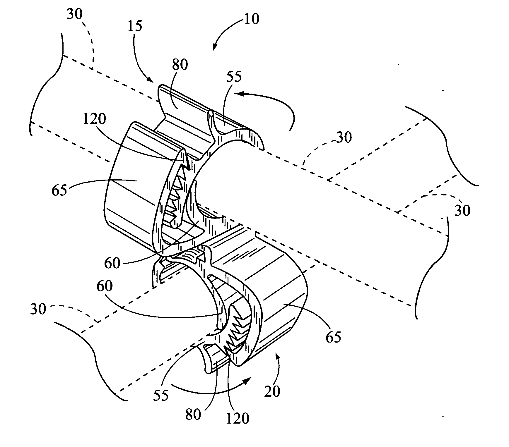
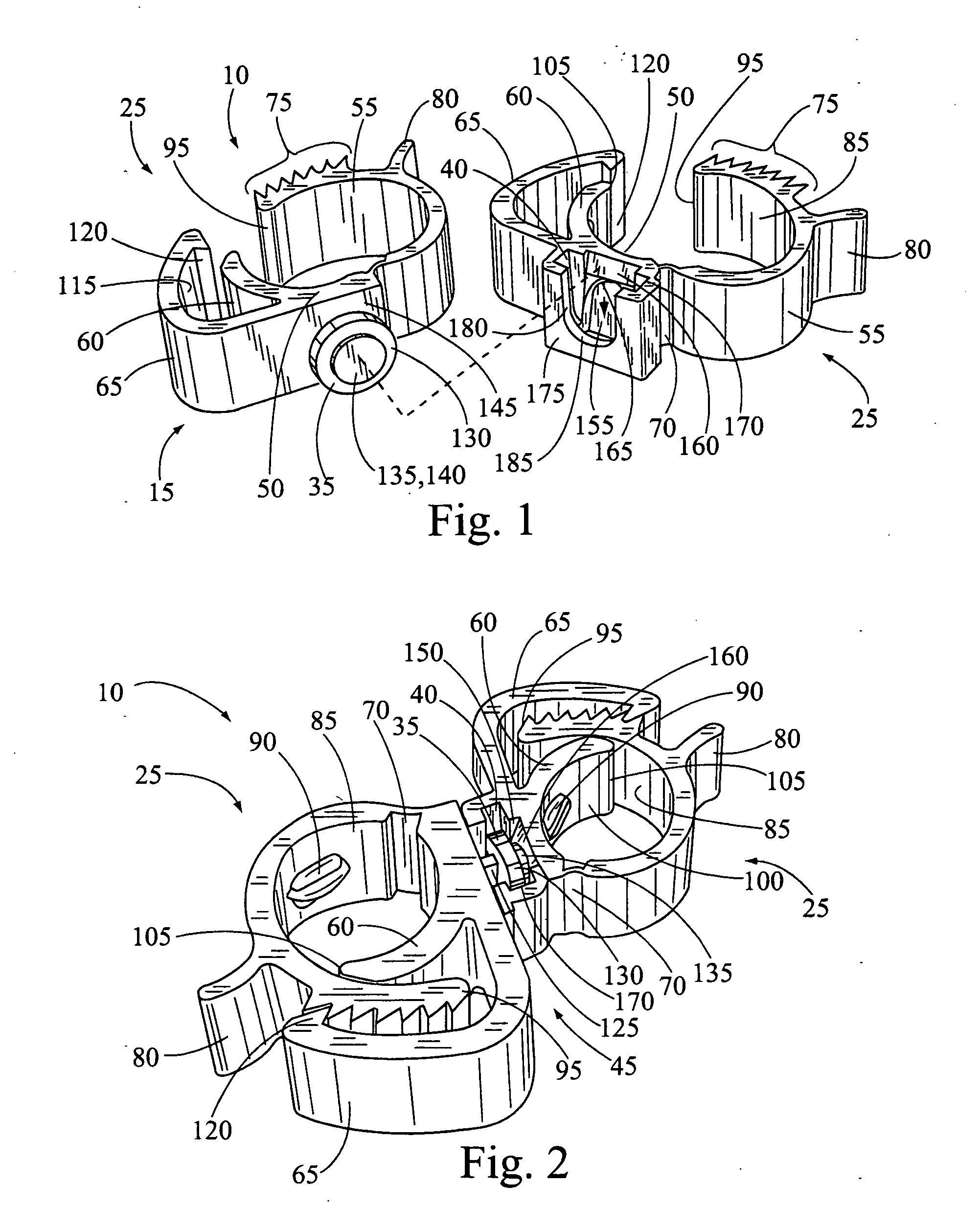
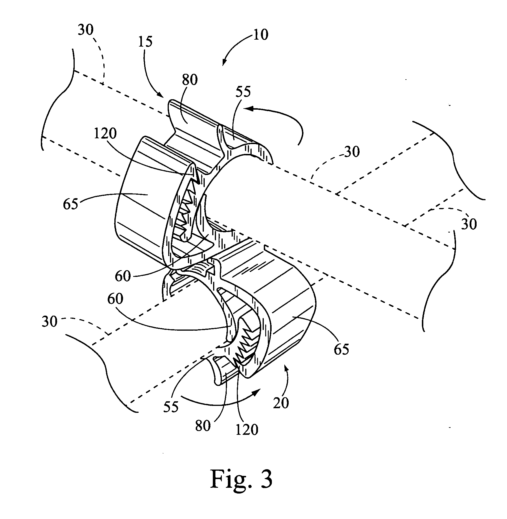
[0017] One embodiment of the fastener of the current invention comprises a two distinct clamp pieces that are pivotally connected to each other, thereby permitting an installer to couple any two pieces of rebar at their respective intersection regardless of the angle formed between the pieces. One embodiment is preferably comprised of a plastic material thereby obviating any rust related problems common with steel wire ties. Additionally, because the fastener physically separates the pieces of rebar joined at an intersection from each other, there isn't a location for excess moisture to pool and simultaneously corrode the pieces at the intersection. Further, because the pieces of rebar are separated, there is a much smaller chance for moisture to wick from one piece to another. Additionally, if two pieces of rebar comprising different base materials are used, their will be no galvanic corrosion between them at the intersection. Another advantage of the one embodiment fastener is tha...


PUM


Abstract

A fastener for joining two pieces of rebar together in a rebar grid used to reinforce subsequently poured concrete is described. The fasteners include two clamp pieces that in certain embodiments completely wrap around a piece of rebar and are tightly secured thereto. Further, each clamp piece can swivel or rotate up to 360 degrees relative to the other clamp piece such that two rebar pieces intersecting at any angle can be coupled together.

Description

REFERENCE TO RELATED APPLICATIONS [0001] This application claims priority to and incorporates herein in its entirety the provisional application No. 60 / 550,703 filed on Mar. 8, 2004 entitled “Swivel Clip rebar Fastener”, and having the same inventor as this application.FIELD OF THE INVENTION [0002] This invention generally relates to reinforced concrete, and more particularly, this invention pertains to a swiveling rebar fastener specifically adapted to secure reinforcement bars (rebar) to one another to form a reinforcement grid or structure over which concrete is subsequently poured. BACKGROUND [0003] Metal reinforcement is typically used in concrete when the concrete is to be used for structural purposes. The reinforcement acts to both hold the concrete together and significantly increase the strength of the resulting concrete structure. When the most common forms of metal reinforcement is rebar. In a typical process of fabricating a reinforced concrete structure, a rebar grid is...

Claims


Application Information

Patent Timeline
IPC IPC(8): E04C5/16
CPCE04C5/163E04C5/167Y10T403/32983Y10T403/7194Y10T403/7176Y10T403/32975
Inventor CARRAHER, JOHN MICHAELNEWTON, TERRY DANIEL
Owner JIFFY CLIP
Why Eureka
Try Eureka