A component connection structure and a display base connection device

A connection structure and component technology, which is applied in the field of component connection structure and display base connection device, can solve the problems of inevitable gaps, poor connection stability, and inability to connect two components together, and achieves great practical significance in production, Easy to assemble and disassemble, good for production applications

Inactive Publication Date: 2019-07-26
TIANJIN SAMSUNG ELECTRONICS CO LTD +1
View PDF7 Cites 0 Cited by
  • Summary
  • Abstract
  • Description
  • Claims
  • Application Information

AI Technical Summary

Problems solved by technology

[0003] Among them, screw fasteners are used for connection. This connection method connects two parts together by screws. When installing and disassembling, the user needs to prepare a professional tool screwdriver (ie, a screwdriver). If there is no accurate professional tool, the user will The two parts cannot be fixedly connected together by screws, and the two parts that have been fixed together by screws cannot be disassembled. Therefore, it brings a lot of inconvenience to the user's work and life, and seriously reduces the user's product experience.
[0004] In addition, the buckle structure is used to connect the two parts together through the buckle, so the buckle will easily fail after repeated assembly and disassembly. Once the buckle fails, the two parts can no longer be snapped together. Fixed together, also bring a lot of inconvenience to the user's work and life
At the same time, due to the requirements of the buckle structure, there will inevitably be a gap between the two parts, so that the two parts cannot be tightly fitted together, and the stability of the connection between the two parts is relatively poor.

Method used


Image

  • A component connection structure and a display base connection device
  • A component connection structure and a display base connection device
  • A component connection structure and a display base connection device

Examples


Embodiment Construction

[0034] In order to enable those skilled in the art to better understand the solution of the present invention, the present invention will be further described in detail below in conjunction with the accompanying drawings and embodiments.

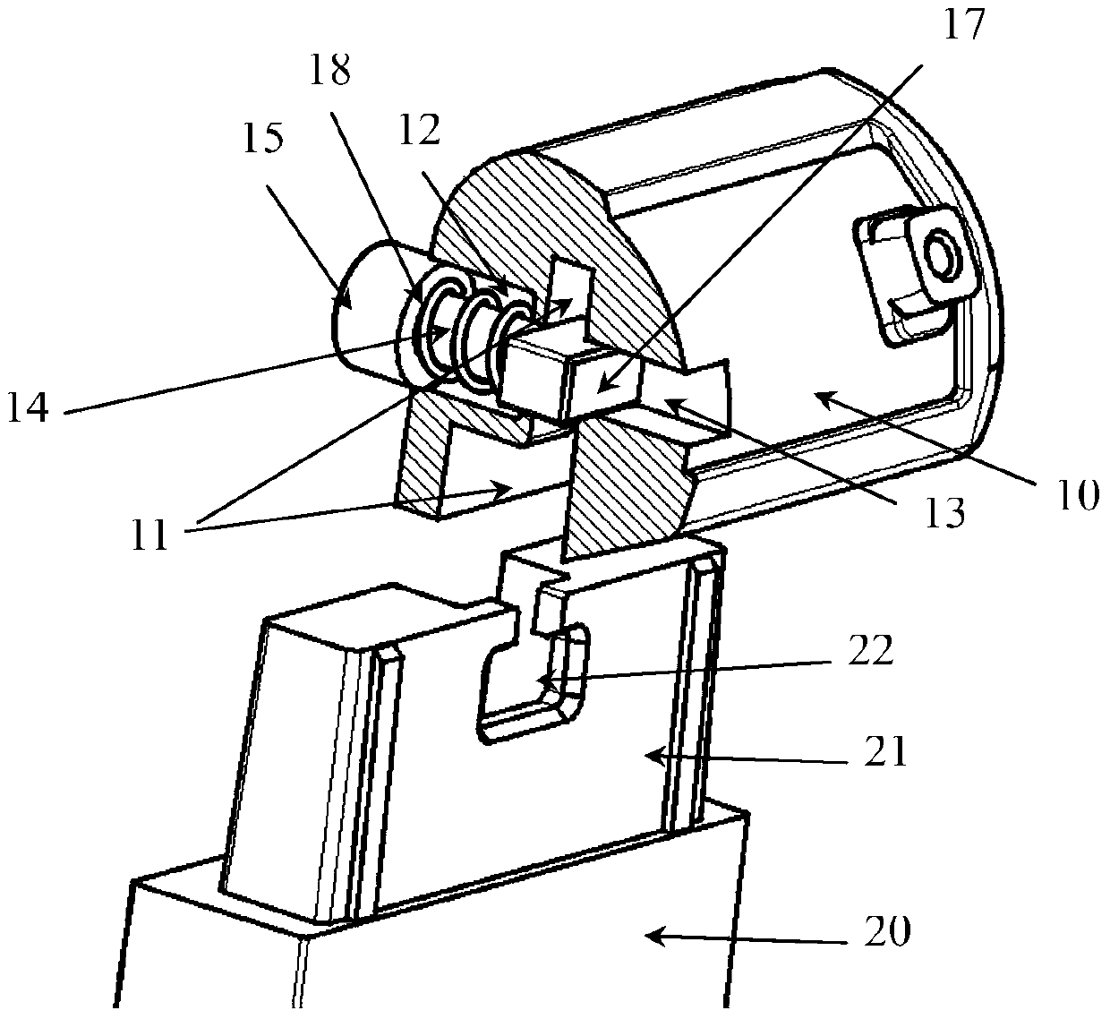
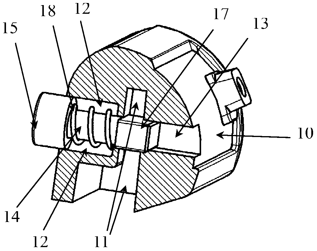
[0035] see figure 1 , the present invention provides a component connection structure, including a first connection piece 10 and a second connection piece 20, and the first connection piece 10 and the second connection piece 20 are installed on the shells of the two components respectively.

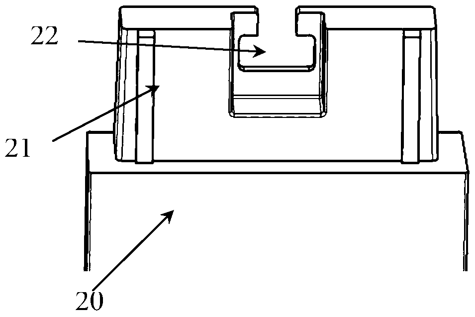
[0036] see also figure 2 , image 3 and Figure 4 , the bottom of the first connector 10 has a concave socket 11, the upper part of the second connector 20 has a connecting rod 21, the socket 11 is formed with the connecting rod 21 on the upper part of the second connector 20 Plug fit.

[0037] The top of the connecting rod 21 has a T-shaped, open connecting groove 22 ; the socket 11 of the first connecting member 10 is provided with a button insta...


PUM


Abstract

The invention discloses a component connecting structure which comprises a first connecting piece (10) and a second connecting piece (20); a sunken inserted connection hole (11) is formed in the bottom of the first connecting piece (10); a connecting rod (21) is arranged at the upper part of the second connecting piece (20); inserted connection matching is formed between the inserted connection hole (11) and the connecting rod (21) at the upper part of the second connecting piece (20); a sliding block (17) capable of transversely moving is arranged in the inserted connection hole (11) of the first connecting piece (10); a connecting groove (22) is formed in the top of the connecting rod (21); and the first connecting piece (10) is provided with a sliding block moving device which enables the sliding block (17) to be selectively clamped in the connecting groove (22). According to the component connecting structure and a display base connecting device, two components can be fixedly connected with each other rapidly, the connection stability is guaranteed, and a user can conveniently assemble and disassemble connection between the two components.

Description

technical field [0001] The invention relates to the field of mechanical technology, in particular to a component connection structure and a display base connection device. Background technique [0002] At present, in order to realize the connection between the two components, the commonly used structure is to use a screw fastener or a buckle structure to connect. [0003] Among them, screw fasteners are used for connection. This connection method connects two parts together by screws. When installing and disassembling, the user needs to prepare a professional tool screwdriver (ie, a screwdriver). If there is no accurate professional tool, the user will The two parts cannot be fixedly connected together by screws, and the two parts fixed together by screws cannot be disassembled. Therefore, it brings a lot of inconvenience to the user's work and life, and seriously reduces the user's product use experience. [0004] In addition, the buckle structure is used to connect the tw...

Claims


Application Information

Patent Timeline
Patent Type & Authority Patents(China)
IPC IPC(8): H04N5/64F16B1/04
CPCF16B1/04F16M11/22F16M2200/02
Inventor 高艳霞耿翠肖
Owner TIANJIN SAMSUNG ELECTRONICS CO LTD
Why Eureka
Try Eureka