Shaft liner structure and automatic teller machine

A technology of automatic teller machine and shaft sleeve, which is applied in the accessories of automatic teller machine, parts and instruments of automatic teller machine, etc., can solve the complex installation and disassembly process of shaft sleeve, which affects the installation accuracy and efficiency of parts on the shaft. Low and other problems, to achieve the effect of good tongue installation stability and simple positioning

Pending Publication Date: 2017-07-18
SHENZHEN YIHUA COMP +2
View PDF4 Cites 1 Cited by
  • Summary
  • Abstract
  • Description
  • Claims
  • Application Information

AI Technical Summary

Problems solved by technology

[0003] The tongue in the cash box of the ATM is generally installed on the separation shaft through the shaft sleeve. The existing shaft sleeve is designed with a center hole. During the installation process, the separation shaft is directly passed through the center hole to be sleeved on the shaft. However, because the shaft sleeve is installed from one end of the shaft to the shaft, it is easy to wear and separate the surface of the shaft during the installation process, which will affect the installation accuracy of other parts on the shaft, and when the shaft sleeve is damaged Or when it needs to be replaced after wear and tear, all other structures on the entire shaft need to be dismantled before the shaft sleeve can be removed and replaced, which leads to a very complicated installation and disassembly process of the shaft sleeve, long installation and maintenance time and low efficiency
At the same time, because the tongue is usually directly assembled on the outer diameter of the shaft sleeve through interference fit, the stability of the tongue is very poor during use.

Method used


Image

  • Shaft liner structure and automatic teller machine
  • Shaft liner structure and automatic teller machine
  • Shaft liner structure and automatic teller machine

Examples


Embodiment Construction

[0028] The technical solutions of the present invention will be further described below in conjunction with the accompanying drawings and through specific implementation methods.

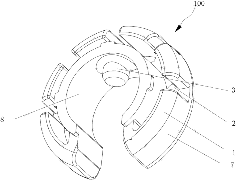
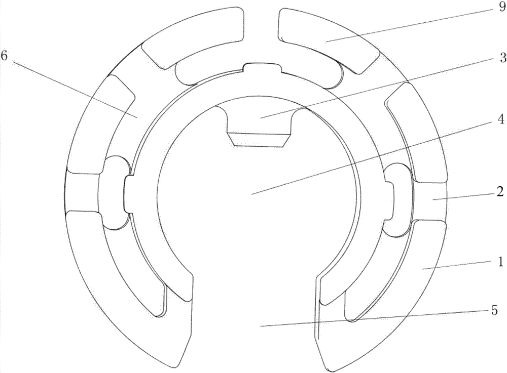
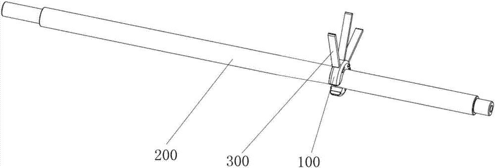
[0029] like Figure 1 to Figure 3 As shown, the bushing structure 100 includes a bushing body 1, a limit post 3 and a slot 2, and the bushing body 1 is provided with a through hole 4 for accommodating the separation shaft 200 and a bayonet for snapping the separation shaft 200 into the through hole 4 5. A limit post 3 is arranged inside the through hole 4, and the limit post 3 is fixedly connected with the bushing body 1. The bushing body 1 is provided with a slot 2 for clamping the tongue 300, and the slot 2 is formed by the bushing body. The outer side 7 extends along the radial direction of the shaft sleeve body 1 to the inner side 8 of the shaft sleeve body.

[0030] Compared with the shaft sleeve in the prior art, it can only penetrate and pass through one end of the separation shaft, and the ...


PUM


Abstract

The invention discloses a shaft liner structure and an automatic teller machine, and belongs to the financial equipment technology field. The shaft liner structure comprises a shaft liner body, a limiting column, and a clamping groove. The shaft liner body is provided with a through hole used for accommodating a shaft and a bayonet used for clamping a separating shaft in the through hole. The limiting column is disposed in the through hole, and is fixedly connected with the shaft liner body. The clamping groove is extended from the outer side surface of the shaft liner body to the inner side surface of the shaft liner body along the radial direction of the shaft liner body. By arranging the through hole and the bayonet in the shaft liner body, the rapid clamping connection and the rapid separation of the shaft liner body and the separation shaft are realized, and therefore the problem of the repairing of the shaft liner requiring the dismounting of all components of the separating shaft is solved. The axial positioning of the separating shaft and the shaft liner structure is realized by the limiting column, and the positioning is simple. Fixed connection between a tongue piece and the shaft liner structure is realized by the clamping groove, and the installation stability of the tongue piece is good. The invention also provides the automatic teller machine comprising the above mentioned shaft liner structure.

Description

technical field [0001] The invention relates to the technical field of financial equipment, in particular to a bushing structure and an automatic cash deposit machine using the bushing structure. Background technique [0002] Automatic teller machine, also known as ATM, is the abbreviation of Automatic Teller Machine. Most ATM machines can also be used for deposits, so they are also called automatic teller machines. ATM is a highly sophisticated electromechanical integration device. Cardholders can use magnetic code cards or smart cards to realize self-service financial transactions such as withdrawing cash, checking deposit balances, transferring funds between accounts, and checking balances. Serve. The ATM can replace the work of the bank counter staff, reduce the work intensity of the bank counter staff, save the time for customers to queue up for business at the bank, and improve the work efficiency of the bank. [0003] The tongue in the cash box of the automatic tell...

Claims


Application Information

Patent Timeline
Patent Type & Authority Applications(China)
IPC IPC(8): G07D11/00G07F19/00
CPCG07D11/10G07F19/201B65H2601/324B65H2404/1114B65H2701/1912
Inventor 徐箭王秋雨
Owner SHENZHEN YIHUA COMP
Why Eureka
Try Eureka