
Protector testing device

A technology of testing devices and protectors, which is applied in the direction of measuring devices, instruments, measuring electricity, etc., can solve problems such as unsafety and danger, and achieve the effects of increasing the safety factor, eliminating contact, and reducing electric shock casualties

Inactive Publication Date: 2017-05-17
国网山东桓台县供电公司
View PDF0 Cites 0 Cited by
  • Summary
  • Abstract
  • Description
  • Claims
  • Application Information

AI Technical Summary

Problems solved by technology

[0002] Usually, when testing residual current protectors, they are behind the switchboard. Due to the small space behind the panel, the tester and guardian cannot squat down. This is unsafe and poses a potential hazard
When testing the residual current protector, it is necessary to pass the test line through the zero-sequence transformer. When passing through the zero-sequence transformer, it is very dangerous and unsafe

Method used


Image

  • Protector testing device

Examples


Embodiment Construction

[0012] The present invention will be further described below in conjunction with the accompanying drawings.

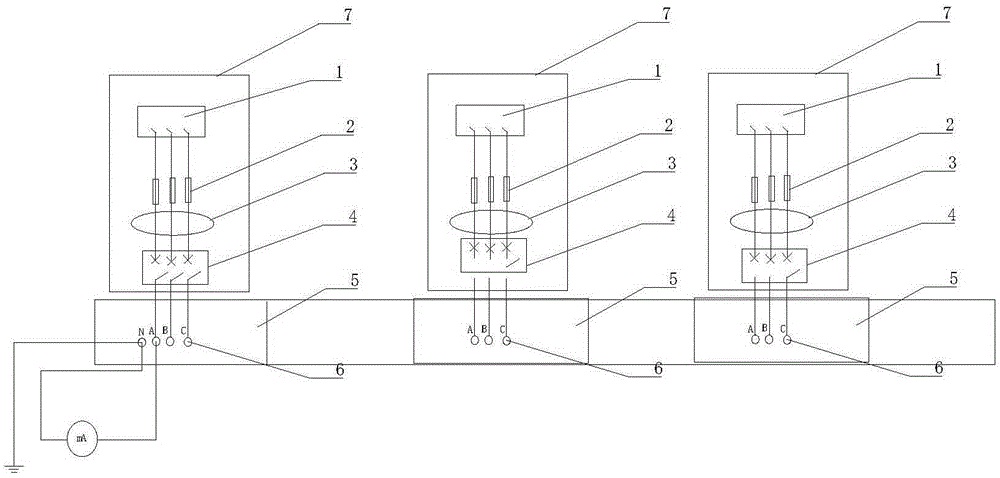
[0013] The invention includes a knife switch 1, a fuse 2, a zero-sequence transformer 3, a ZD47-32A circuit breaker 4, a bottom plate 5 of a distribution box and a terminal 6, and the bottom plate 5 of the distribution box is provided with a There are 10 through holes in the terminal 6, and the terminal 6 is fixedly connected to the bottom plate 5 of the distribution box with threads, and a fixing groove is provided on the front side box plate of the distribution box on the upper side of the bottom plate 5 of the distribution box Plate 7, fixed groove Plate 7 is provided with knife switch 1, fuse 2, zero-sequence transformer 3, ZD47-32A circuit breaker 4, knife switch 1, fuse 2, zero-sequence transformer at equal intervals from top to bottom 3. The ZD47-32A circuit breaker 4 is electrically connected to the terminal 6.

[0014] The wires of the fuse 2 and the ZD47-32A...


PUM


Abstract

The invention aims to provide an aftercurrent protector testing device which is high in safety performance and good for personal safety protection. The protector testing device includes a knife switch, a fuse, a zero sequence mutual inductor, a ZD47-32A circuit breaker, a power distribution box bottom board and wiring posts. The power distribution box bottom board is provided with 10 through holes used for fixedly connecting with 10 wiring posts. The wiring posts are connected to the power distribution box bottom board fixedly through threads. A fixed groove board is arranged on a front box board of a power distribution box body on the upper side of the power distribution box bottom board. The knife switch, the fuse, the zero sequence mutual inductor, the ZD47-32A circuit breaker are arranged on the fixed groove board from top down at equal space. The knife switch, the fuse, the zero sequence mutual inductor and the ZD-A circuit breaker are electrically connected with the wiring posts. According to the invention, aftercurrent protection testing can be implemented completely in the front side of the power distribution box body, so that the safety coefficient is increased. Contact with electrified parts behind a power distribution plate is avoided, so that injuries and deaths due to electric shock can be reduced.

Description

technical field [0001] The invention relates to the technical field of power testing, in particular to a testing device for a residual current protector in a distribution box. Background technique [0002] Usually, when testing residual current protectors, they are behind the switchboard. Due to the small space behind the panel, the tester and guardian cannot squat down. This is unsafe and creates potential danger. When testing the residual current protector, it is necessary to pass the test line through the zero-sequence transformer. When passing through the zero-sequence transformer, it is very dangerous and unsafe. Contents of the invention [0003] The purpose of the present invention is to provide a residual current protector testing device with high safety performance and better personal safety protection. [0004] In order to achieve the above object, the technical solution adopted by the present invention is: the present invention includes a knife switch, a fuse,...

Claims


Application Information

Patent Timeline
Patent Type & Authority Applications(China)
IPC IPC(8): G01R31/00
Inventor 孟东瑞张克徐琛崔学东张海峰窦钦东
Owner 国网山东桓台县供电公司
Learn More