
Marine BDS receiving device in-band and band edge continuous wave interference threshold determination method

A technology for receiving equipment and wave interference, which is applied in radio wave measurement systems, satellite radio beacon positioning systems, and measurement devices, and can solve problems such as reliability decline in outdoor and microwave anechoic chamber test methods, difficulty in accurate measurement and estimation, etc.

Active Publication Date: 2017-05-17
NO 20 RES INST OF CHINA ELECTRONICS TECH GRP
View PDF4 Cites 10 Cited by
  • Summary
  • Abstract
  • Description
  • Claims
  • Application Information

AI Technical Summary

Problems solved by technology

[0009] In order to overcome the deficiencies in the prior art that the outdoor test method is easily affected by other unexpected and unknown radio frequency interference from the external environment, which leads to a decrease in the reliability of the test results and the difficulty in accurately measuring and estimating the spatial attenuation of the signal in the outdoor and microwave anechoic test methods, the present invention provides A method for determining the threshold value of in-band and band-side continuous wave interference, which is the formulation and implementation of anti-in-band and band-side continuous wave interference performance requirements in the standard "Marine BDS receiving equipment performance requirements, test methods and required test results". Provide a basis for the establishment of the corresponding interference test environment conditions

Method used


Image

  • Marine BDS receiving device in-band and band edge continuous wave interference threshold determination method
  • Marine BDS receiving device in-band and band edge continuous wave interference threshold determination method
  • Marine BDS receiving device in-band and band edge continuous wave interference threshold determination method

Examples


Embodiment Construction

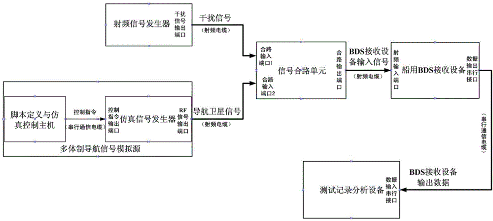
[0025] The present invention will be further described below in conjunction with the accompanying drawings and embodiments, and the present invention includes but not limited to the following embodiments.

[0026] The method for determining the in-band and band-side continuous wave interference threshold of the marine BDS receiving equipment provided by the present invention is specifically as follows:

[0027] Step 1 Test environment setup

[0028] Test location: Indoor (non-microwave anechoic environment).

[0029] Main test equipment: marine BDS receiving equipment (one set), multi-system navigation signal simulation source (including script definition and simulation control host and simulation signal generator, one set), radio frequency signal generator (one set), signal combiner unit (one), test record analysis equipment (one).

[0030] refer to figure 1 , the script definition in the multi-system navigation signal simulation source is connected with the simulation con...


PUM

PropertyMeasurementUnit
Elevation angleaaaaaaaaaa

Abstract

The present invention provides a marine BDS (BeiDou Navigation Satellite System) receiving device in-band and band edge continuous wave interference threshold determination method. The multi-system navigation signal simulation source is employed to generate satellite signals, a radio-frequency signal generator is employed to generate interference signals, satellite signals and interference signals are transmitted to a signal combination unit through radio-frequency cables to perform channel combination, and the combination signals are transmitted to a marine BDS receiving device through the radio-frequency cables to determine the interference threshold. The marine BDS receiving device in-band and band edge continuous wave interference threshold determination method is not influenced by other undesirable unknown radio-frequency interferences of the external environment so as to accurately measure and estimate the space attenuation of signals.

Description

technical field [0001] The invention belongs to a method for testing the anti-interference performance of marine Beidou Navigation Satellite System (BDS) receiving equipment, and relates to a method for determining an in-band and band-side continuous wave interference threshold, which is used for "performance requirements and testing of marine BDS receiving equipment." Methods and required test results" standard, the establishment of requirements for anti-in-band and band-side continuous wave interference performance and the establishment of corresponding test environment conditions. Background technique [0002] Global Navigation Satellite System (GNSS) is a satellite-based radio navigation system that uses artificial satellites as navigation platforms to provide global users with all-weather, real-time, continuous, high-precision navigation, positioning and timing services. Build and maintain the infrastructure essential to military security. Due to the low power of the s...

Claims


Application Information

Patent Timeline
IPC IPC(8): G01S19/21G01S19/23
CPCG01S19/21G01S19/23
Inventor 耿峰
Owner NO 20 RES INST OF CHINA ELECTRONICS TECH GRP
Learn More