Orthopedic device

A shaping device and shaping plate technology, which is applied in battery assembly machines, sustainable manufacturing/processing, and primary battery manufacturing equipment, etc., can solve the problems of slow shaping speed, speed up shaping, and avoid tension or even breaking , The effect of simplifying the device

Active Publication Date: 2019-02-19
WUXI LEAD INTELLIGENT EQUIP CO LTD
View PDF4 Cites 0 Cited by
  • Summary
  • Abstract
  • Description
  • Claims
  • Application Information

AI Technical Summary

Problems solved by technology

However, when the current shaping mechanism is shaping the cell (object), it only targets one cell (object) at a time, and the shaping speed is slow.

Method used


Image

  • Orthopedic device
  • Orthopedic device
  • Orthopedic device

Examples


Embodiment 1

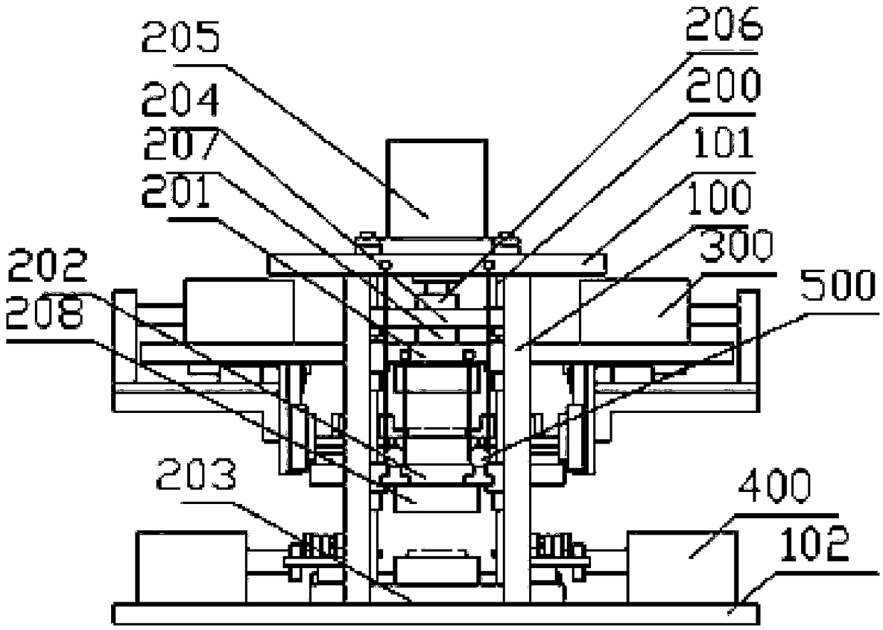
[0032] Such as figure 1 , image 3 , Figure 4 As shown, the shaping device of the present invention mainly includes a support frame, a pressing mechanism, a side pressing mechanism and a pulley mechanism.

[0033] The support frame mainly includes a support column 100 , an upper support plate 101 and a lower support plate 102 . There are four supporting columns 100, respectively corresponding to the four corners of the upper supporting plate 101 and the lower supporting plate 102. The lower part of the supporting column 100 is fixedly connected to the lower supporting plate 102, and the upper part is fixedly connected to the upper supporting plate 101 to provide support for the shaping device. .

[0034] The pressing mechanism mainly includes guide column 200 , first pressing plate 201 , second pressing plate 202 , supporting plate 203 , guiding plate 204 , electric cylinder 205 , floating joint 206 , pressure sensor 207 , and vertical heating and pressing plate 208 . The...

Embodiment 2

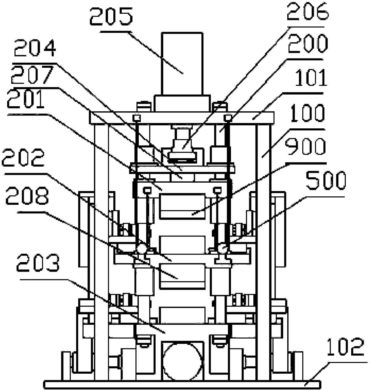
[0046] Such as figure 2 As shown, the shaping device of the present invention also includes a support frame, a pressing mechanism, a side pressing mechanism and a pulley mechanism. The difference between the shaping device in Embodiment 2 and the shaping device in Embodiment 1 mainly lies in the side pressing mechanism. , the following will mainly introduce the lateral pressure mechanism in Embodiment 2. The side pressure mechanism in Example 2 uses a reducer to realize power splitting, and then combines some connection mechanisms to realize the shaping of the sides of the battery cells in the two shaping spaces through a motor, which simplifies the device and reduces the cost of the device. Effect.

[0047] Such as Figure 6 As shown, the lateral pressure mechanism in Embodiment 2 mainly includes a lateral pressure motor 600, a reducer 601, a lead screw 602, a nut 603, a first connecting plate 604, a first bearing plate 605, a vertical plate 606, and a second connecting pl...


PUM


Abstract

The invention relates to a shaping device, which is characterized in that it includes a support frame, a pressing mechanism and a side pressing mechanism; A first shaping space is formed between the pressing plate and the second pressing plate, a second shaping space is formed between the second pressing plate and the support plate, vertical Shaping plate, the first pressing plate is connected to the output end of the pressing drive device; the first pressing plate and the second pressing plate are connected through a connecting member; the lateral pressing mechanism includes a first side pressing shaping plate capable of sliding horizontally and vertically and A second side pressure shaping plate that can slide horizontally, the first side pressure shaping plate is installed on both sides of the first shaping space, and the second side pressure shaping plate is installed on both sides of the second shaping space; the first side pressure shaping plate The plate and the second side pressure shaping plate are connected to the output of the side pressure drive device. The invention can accelerate the speed of shaping.

Description

technical field [0001] The invention relates to a shaping device, in particular to a shaping device capable of accelerating the shaping speed, and belongs to the technical field of automation equipment. Background technique [0002] In the field of automation equipment technology, a shaping mechanism is often required to press the object to the target state. For example, in the production of lithium batteries, after the pole pieces are wound, a shaping mechanism is needed to compact or press the battery cell to a certain shape. However, when the current shaping mechanism is shaping the cell (object), it only targets one cell (object) at a time, and the shaping speed is slow. Contents of the invention [0003] The purpose of the present invention is to overcome the deficiencies in the prior art and provide a shaping device that can speed up the shaping. [0004] According to the technical solution provided by the present invention, the shaping device is characterized by: c...

Claims


Application Information

Patent Timeline
Patent Type & Authority Patents(China)
IPC IPC(8): H01M10/04H01M6/00
CPCH01M6/005H01M10/0404Y02P70/50
Inventor 孙坤坤
Owner WUXI LEAD INTELLIGENT EQUIP CO LTD
Why Eureka
Try Eureka