Control system for hybrid vehicle

A technology of hybrid electric vehicle and control system, which is applied to the layout of multiple different prime movers of hybrid electric vehicles and general power plants, and traction driven by engines, etc., which can solve problems such as insufficient driving force and driver discomfort, and achieve Effect to prevent decline of driving force

Inactive Publication Date: 2017-05-17
TOYOTA JIDOSHA KK
View PDF7 Cites 4 Cited by
  • Summary
  • Abstract
  • Description
  • Claims
  • Application Information

AI Technical Summary

Problems solved by technology

So the driving force for rotating the drive wheels will be insufficient, so the driver may feel uncomfortable

Method used


Image

  • Control system for hybrid vehicle
  • Control system for hybrid vehicle
  • Control system for hybrid vehicle

Examples


Embodiment Construction

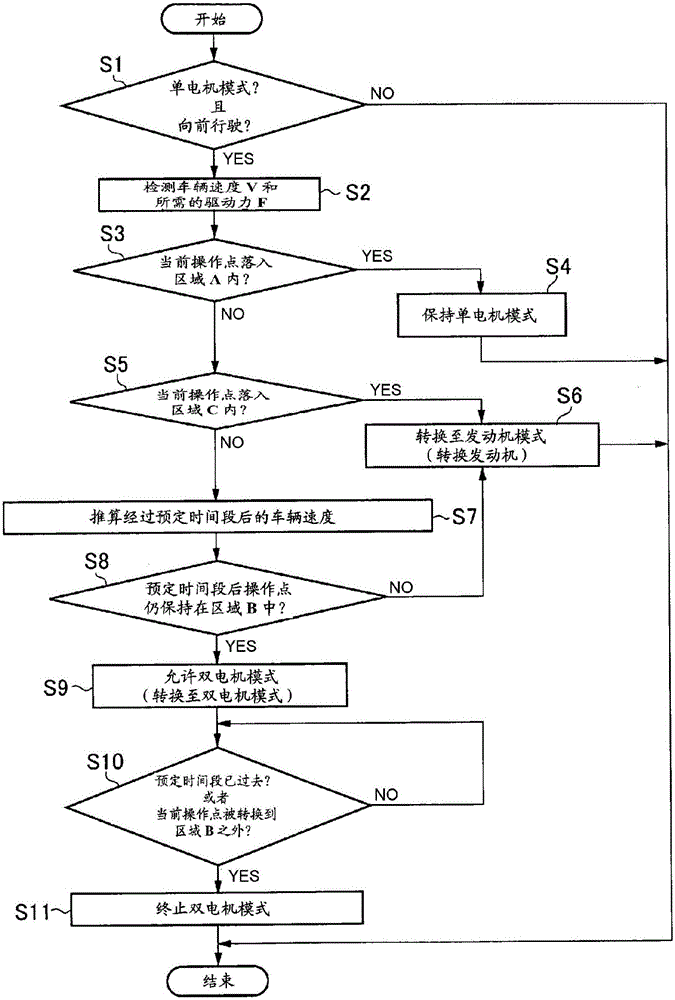
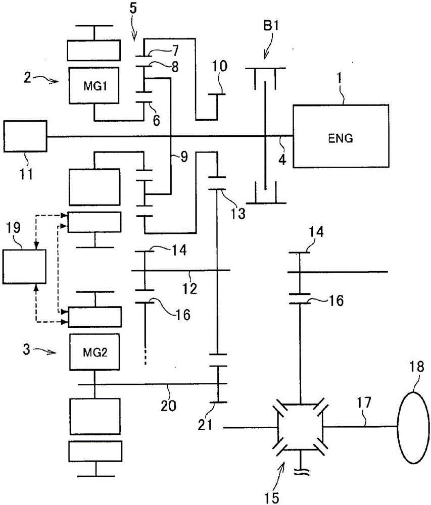
[0030] now refer to figure 2 , shows a first example of a hybrid vehicle to which the control system of the preferred example is applied. figure 2 The illustrated hybrid vehicle includes a prime mover comprising an engine 1 (in figure 2 referred to as "ENG") and the first motor / generator 2 and the second motor / generator 3 (in figure 2 referred to as "MG1" and "MG2"). A hybrid vehicle can operate in an appropriate operating mode selected from an engine mode, a dual-motor mode, and a single-motor mode, in which the vehicle is powered by the engine 1; in a dual-motor mode, the vehicle is powered by the first motor / generator 2 and the second motor / generator 3, while the engine 1 is stopped; in single motor mode, the vehicle is powered by either the first motor / generator 2 and the second motor / generator 3, while the engine 1 stop.

[0031]An output shaft 4 of the engine 1 is connected to a power split device 5 . The power distribution device 5 is a single-pinion type plane...


PUM


Abstract

A control system for a hybrid vehicle configured to avoid unintentional reduction in a driving force is provided. The control system is configured to estimate a vehicle speed after a predetermined period of time during propulsion of the vehicle under single-motor mode (step S7), and to shift the operating mode directly from the single-motor mode to an engine mode while skipping a dual-motor mode, if a current operating point of the vehicle enters into an operating region where both of the second mode and the third mode are available but the operating mode is expected to be further shifted to the engine mode (step S6).

Description

technical field [0001] The present invention relates to a control system for a hybrid vehicle which controls a prime mover comprising an engine and an electric motor(s) or a motor / generator (motor / generator), and more particularly relates to A control system for a hybrid vehicle configured to switch operating modes of the vehicle. Background technique [0002] JP-A-2008-265598 and JP-A-2000-023310 disclose a power system of a two-motor hybrid vehicle including a motor / generator for controlling engine speed and electric power generated by the motor / generator driven motor. In such a hybrid system, an engine and a motor / generator are respectively connected to a power distribution device adapted to perform different actions among three rotating elements. The motor is connected to an output member of the power split device, which is also connected to drive wheels through a gear train. The motor / generator is electrically connected to the motor to deliver generated electricity t...

Claims


Application Information

Patent Timeline
Patent Type & Authority Applications(China)
IPC IPC(8): B60K6/48B60W10/08B60W20/40B60W20/00B60K6/445B60W20/11B60W10/06B60W40/105B60W40/107B60L50/16
CPCB60K6/445B60K6/48B60W10/06B60W10/08B60W20/00B60W20/40B60W40/105B60W40/107B60W2510/244B60W2520/10B60W2520/105B60W2710/0666B60W2710/083B60W2552/15B60W20/11B60L58/12Y02T10/62Y02T10/70Y02T10/72Y10S903/905Y10S903/906Y10S903/907Y10S903/911Y10S903/914B60K6/24B60K6/26B60K6/28B60K6/365B60K6/387B60K6/442B60W10/02B60W10/115B60W20/20B60W2510/0208B60W2510/06B60W2510/08B60W2510/1015B60W2510/105B60W2510/246B60W2710/021B60W2710/06B60W2710/1011B60W2710/105
Inventor 坂本英圣
Owner TOYOTA JIDOSHA KK
Why Eureka
Try Eureka