Bus bar bending mechanism

A bending mechanism and bus bar technology, applied in the field of mechanical devices, can solve the problems of inability to control the crease of the bus bar, impossible to meet the production requirements of various specifications of battery slices, and inability to change the surface topography of the bus bar, etc. scar effect

Inactive Publication Date: 2017-05-24
CHENGDU JUZHI IND DESIGN
View PDF6 Cites 2 Cited by
  • Summary
  • Abstract
  • Description
  • Claims
  • Application Information

AI Technical Summary

Problems solved by technology

[0002] At present, there are various specifications and thicknesses of domestic battery sheets. Most of the bending mechanisms of ordinary solar cell stringers cannot control the crease of the bus bar and cannot change the surface morphology of the bus bar, so they can only be used for the produ

Method used


Image

  • Bus bar bending mechanism
  • Bus bar bending mechanism

Examples


Embodiment Construction

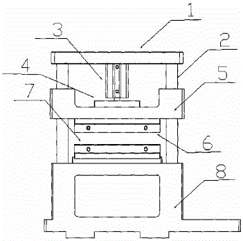
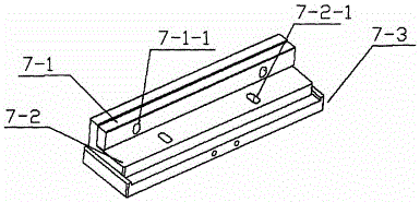
[0012] Below in conjunction with accompanying drawing, the present invention will be further described: as figure 1 with 2 As shown, a bus bar bending mechanism, the bending mechanism is composed of a fixed plate 1, a guide rod 2, a cylinder 3, a transition 4, a connecting plate 5, an upper pressing block 6, a lower pressing block 7 and a supporting plate 8, The upper end of the guide rod 2 is fixed on both sides of the fixed plate 1, the lower end is fixed on both sides of the support plate 8, the cylinder 3 is fixed at the center below the fixed plate 1, and the ejector rod at the head of the cylinder 3 is fixed in the middle of the connecting plate 5 through the transition plate 4. Both ends of the connecting plate 5 are fixed on the guide rod 2 through two bearings, and can freely move up and down. The connecting plate 5 is a U-shaped plate, the upper pressing block 6 is fixed at the middle position below the connecting plate 5, and the lower pressing block 7 is fixed on t...


PUM


Abstract

The invention relates to a bus bar bending mechanism. The bus bar bending mechanism is composed of a fixed plate, guide rods, an air cylinder, a transition plate, a connecting plate, an upper pressing block, a lower pressing block and a supporting plate. Micro protrusions in array distribution are arranged on the whole lower surface of the upper pressing block, and pits corresponding to the micro protrusions of the upper pressing block are formed in the whole upper surface of the lower pressing block. After a bus bar is in place through the bending mechanism, the upper pressing block presses the bus bar downwards to complete bending motion. The height of a cushion block on the pressing block can be adjusted freely, the production requirements of various solar battery cells of different specifications can be met, and meanwhile the light reflection characteristic and attractiveness of the bus bar can be improved.

Description

technical field [0001] The invention relates to a mechanical device, in particular to a bus bar bending mechanism. Background technique [0002] At present, there are various specifications and thicknesses of domestic solar cells. Most of the bending mechanisms of ordinary solar cell stringers cannot control the creases of the bus bars and cannot change the surface morphology of the bus bars, so they can only be used for the production of a single Variety of battery strings is basically impossible to meet the production needs of batteries of various specifications. Therefore, a bus bar bending mechanism is provided to effectively control the crease and change the surface morphology of the bus bar to meet different needs. Contents of the invention [0003] In order to solve the shortcomings of the existing bus bar bending mechanism, a bus bar bending mechanism is proposed, which is composed of a fixed plate, a guide rod, a cylinder, a transition plate, a connecting plate, a...

Claims


Application Information

Patent Timeline
IPC IPC(8): B21D5/01
CPCB21D5/01
Inventor 文国栋
Owner CHENGDU JUZHI IND DESIGN
Why Eureka
Try Eureka