
Accurate positioning industrial mechanical claw

An industrial mechanical claw and precise positioning technology, applied in the direction of manipulators, manufacturing tools, chucks, etc., can solve the problems of no protection, difficult operation, loss of power of mechanical claws, etc., and achieve the effect of avoiding insufficient clamping force

Pending Publication Date: 2017-05-24
张赫
View PDF0 Cites 10 Cited by
  • Summary
  • Abstract
  • Description
  • Claims
  • Application Information

AI Technical Summary

Problems solved by technology

[0002] At present, in the hoisting of cranes, mechanical claws are one of the indispensable equipment. The usual mechanical claws are composed of multi-links. The main shaft is driven by the cylinder to drive the mechanical claws to separate or close. This kind of mechanical claws brings The problem is that multiple connecting rods need to be controlled at the same time, so the positioning is often inaccurate, and it also brings difficulties to the operation. When one of the connecting rods fails, the entire mechanical claw will lose power, and there is no protective power to keep the mechanical claw To maintain the clamping state, we propose a precisely positioned industrial mechanical claw to solve the above problems

Method used


Image

  • Accurate positioning industrial mechanical claw
  • Accurate positioning industrial mechanical claw
  • Accurate positioning industrial mechanical claw

Examples


Embodiment Construction

[0019] The following will clearly and completely describe the technical solutions in the embodiments of the present invention with reference to the accompanying drawings in the embodiments of the present invention. Obviously, the described embodiments are only some, not all, embodiments of the present invention. Based on the embodiments of the present invention, all other embodiments obtained by persons of ordinary skill in the art without making creative efforts belong to the protection scope of the present invention.

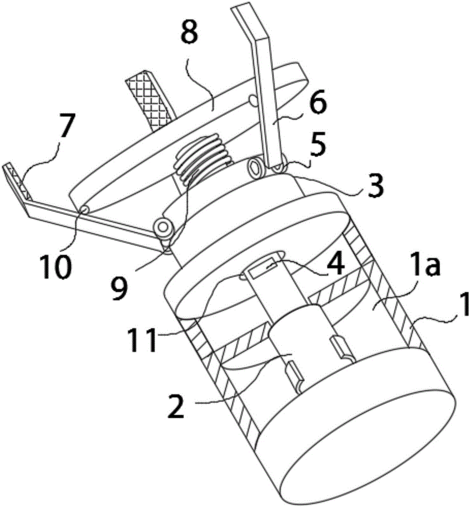
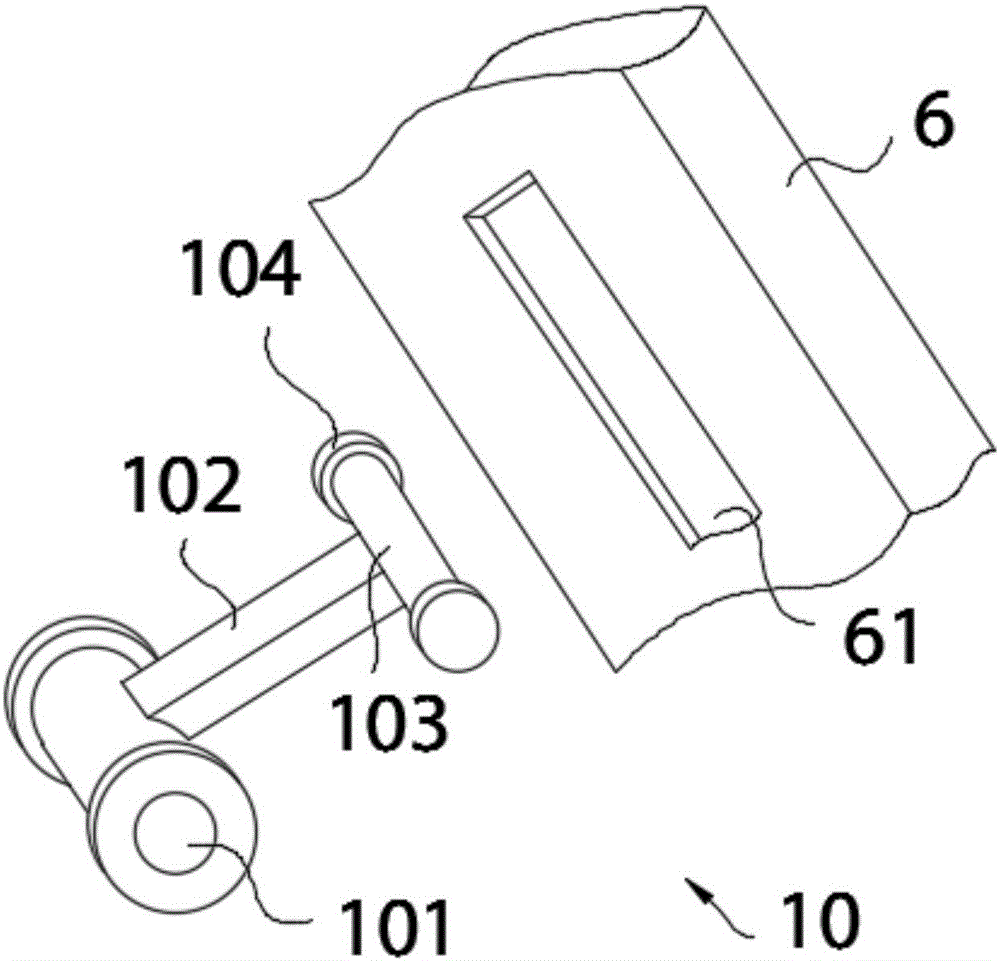
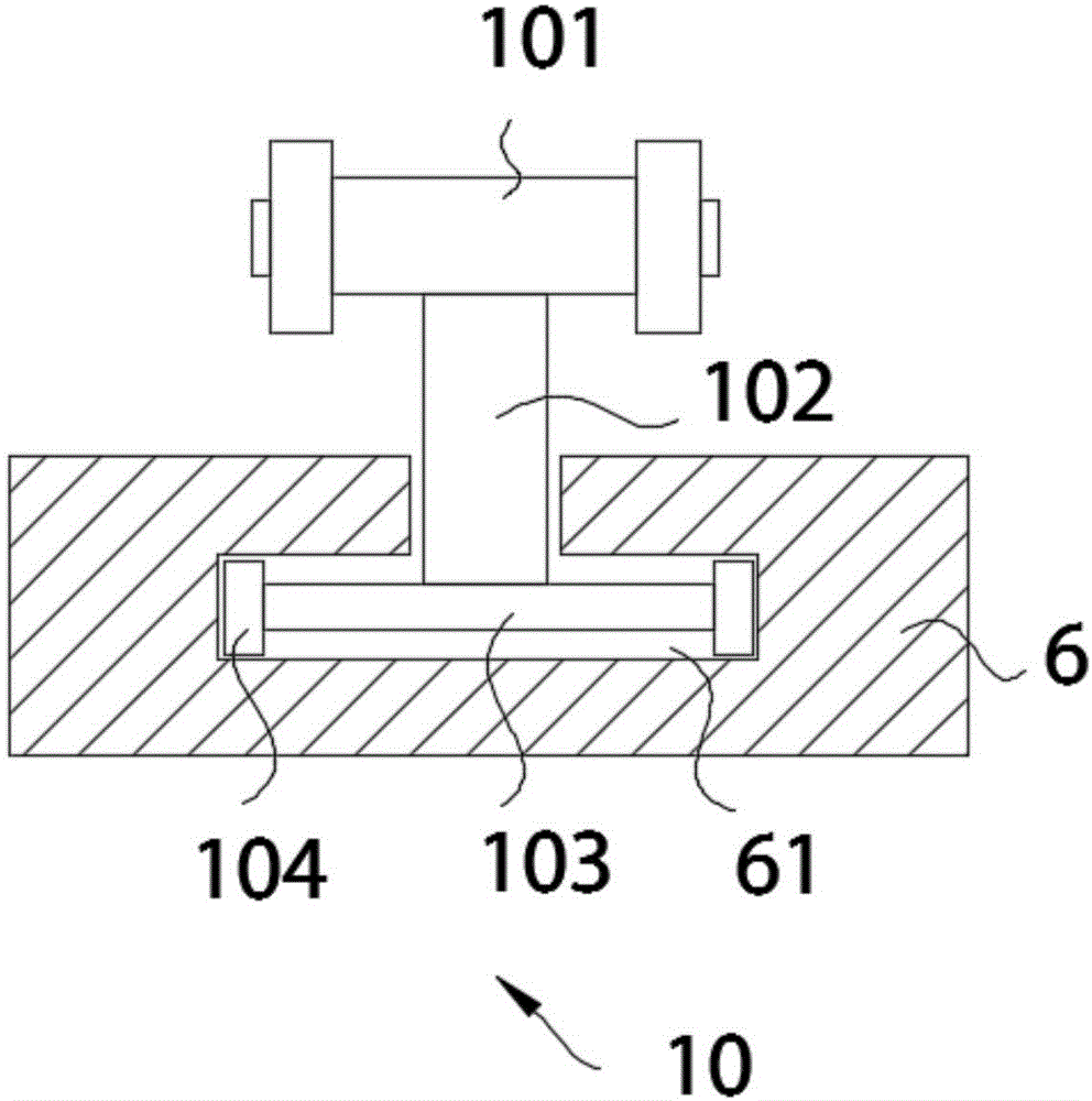
[0020] see Figure 1-5 , the present invention provides a technical solution: a precisely positioned industrial mechanical claw, including a head-end mechanical arm 1, a push rod cavity 1a is provided in the head-end mechanical arm 1, a hydraulic push rod 2 is provided in the push rod cavity 1a, The hydraulic push rod 2 is electrically connected to the power supply through the controller, and the controller controls the drive of the hydraulic push rod 2 to mak...


PUM


Abstract

The invention discloses an accurate positioning industrial mechanical claw which comprises a front end mechanical arm and a hydraulic push rod. A mechanical claw base is fixedly arranged at the upper end of the front end mechanical arm, a mechanical claw body is movably connected to the side face of the upper end of the mechanical claw base through a mechanical claw rotating shaft and is provided with a driving rod device, and the driving rod device is movably installed on the side face of a driving disc; and in addition, a spring is wound around the hydraulic push rod. By means of the structure, the hydraulic push rod is driven by a controller, the driving disc vertically moves accordingly, and therefore the driving rod device moves in a driving groove of the mechanical claw body, and the mechanical claw body is opened and closed to conduct clamping transportation on cargoes; a pressure sensor can display the value of pressure across the cargoes and the mechanical claw body and displays the value on a pressure displayer, when the pressure reaches a certain value, the mechanical claw body can be ascended, and accurate positioning of the mechanical claw body is achieved; and when the hydraulic push rod breaks down and losses power, the spring extrudes the driving disc under the self high intensity, and the mechanical claw body keeps the clamping state.

Description

technical field [0001] The invention relates to the technical field of industrial machinery, in particular to an industrial machinery claw for precise positioning. Background technique [0002] At present, in the lifting of the crane, the mechanical claw is one of the indispensable equipment. The usual mechanical claw is composed of multi-links. The main shaft is driven by the cylinder to drive the mechanical claw to separate or close. This mechanical claw brings The problem is that multiple connecting rods need to be controlled at the same time, so the positioning is often inaccurate, and it also brings difficulties to the operation. When one of the connecting rods fails, the entire mechanical claw will lose power, and there is no protective power to keep the mechanical claw To maintain the clamping state, we propose a precisely positioned industrial mechanical claw to solve the above problems. Contents of the invention [0003] The object of the present invention is to ...

Claims


Application Information

Patent Timeline
Patent Type & Authority Applications(China)
IPC IPC(8): B25J15/00B25J19/02
CPCB25J15/0023B25J19/02
Inventor 张赫
Owner 张赫
Learn More