Up-down reciprocating pedaling type bicycle

A technology of bicycles and bicycle racks, which is applied to vehicle parts, riders' driving, transportation and packaging, etc. It can solve the problems of heavy operation, inability to form rotational torque, and difficult adjustment of pedaling rotational torque, so as to achieve easy acceptance and convenience for normal riding line effect

Pending Publication Date: 2017-05-24
苏州厚点工业技术有限公司
View PDF0 Cites 0 Cited by
  • Summary
  • Abstract
  • Description
  • Claims
  • Application Information

AI Technical Summary

Problems solved by technology

[0003] But there are also major disadvantages. Since the two pedal arms need to be set at 180°, when riding, the bicycle needs to have a certain speed before the two pedals can cross the top dead center and bottom dead center to form a circular motion. , to complete a relatively stable pedaling force output, and only when the pedal is stepped forward within an angle range of about 100° after crossing the top dead center, the pedaling force output can be achieved, and it is difficult to adjust the angle of most of the pedaling force to be close to the outside of the sprocket The circular tangent direction is used to form a larger pedaling torque, only about 50° angle range can produce a large pedaling torque, and the rest of the 260° angle rotation is basically useless work, and because of the work done by the pedal force in each circle The angle is small and it must be rotated once to do work once, resulting in a serious waste of pedaling force, and is limited by the movement distance of the human legs and the minimum ground clearance of the pedals, the design length of the pedal arm can only be limited within a certain range , unable to form a larger rotational moment, which eventually causes the rider to consume a lot of physical energy when riding, laborious when going uphill, and heavy to operate

Method used


Image

  • Up-down reciprocating pedaling type bicycle
  • Up-down reciprocating pedaling type bicycle
  • Up-down reciprocating pedaling type bicycle

Examples


Embodiment Construction

[0026] Now, embodiments according to the present invention will be described in detail, examples of which are illustrated in the accompanying drawings. Hereinafter, the embodiments are described in order to explain the present general inventive concept by referring to the figures.

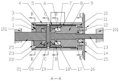
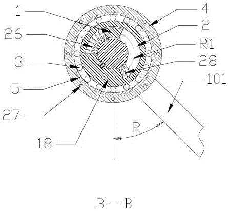
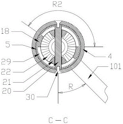
[0027] Such as Figure 1 to Figure 4 as shown,

[0028]Described a kind of up and down reciprocating pedal type bicycle comprises bicycle frame 100, sprocket wheel 15, pedal arm 101, in order to produce, assemble, install more conveniently, be provided with inner sleeve 5 in the steel pipe 4 of bicycle frame 100 axis , the inner sleeve 5 is provided with a left central shaft 25 and a right central shaft 13, wherein the left central shaft 25 is rigidly connected with the left central shaft sleeve 18, and the left central shaft 25 passes through and is fixed on the central shaft steel pipe 4 of the vehicle frame 100 One end of the left end cover 23 is fixedly installed with a pedal arm 101, and the...


PUM


Abstract

In order to solve the deficiencies of existing bicycles, the invention provides an up-down reciprocating pedaling type bicycle which can produce continuous pedaling force output by alternatively pedaling left and right pedals to and fro, and can easily acquire the bigger pedaling force output by adjusting a pedaling angle and controlling a reciprocating alternative swing angle. According to the bicycle provided by the invention, an existing pedaling circular motion with low bicycle pedaling force transmission efficiency is replaced by the up-down reciprocating pedaling; the bicycle provided by the invention has the advantages of being high in pedaling force utilization rate, capable of greatly reducing physical consumption, free of dead zone in pedaling, convenient to ride, simple in structure, slight in appearance modification and easy to be accepted by a rider.

Description

technical field [0001] The invention belongs to the technical field of bicycles and relates to an up and down reciprocating pedal bicycle. Background technique [0002] The basic structure of the existing bicycle is that pedal arms and pedals are fixedly installed at the two ends of the central shaft at the lower part of the bicycle frame, and the sprocket wheel on the central shaft is driven to rotate by the circular circulation of the rider's both feet, and through The chain drives the sprocket wheel on the rear wheel to rotate to push the bicycle forward, which has the advantages of simple structure and the like, and brings great convenience to people's travel. [0003] But there are also major disadvantages. Since the two pedal arms need to be set at 180°, when riding, the bicycle needs to have a certain speed before the two pedals can cross the top dead center and bottom dead center to form a circular motion. , to complete a relatively stable pedaling force output, and...

Claims


Application Information

Patent Timeline
Patent Type & Authority Applications(China)
IPC IPC(8): B62M1/24B62M1/28
CPCB62M1/24B62M1/28
Inventor 李钢
Owner 苏州厚点工业技术有限公司
Why Eureka
Try Eureka