Quenching cooling device for large seal head

A technology of cooling device and head, applied in the direction of quenching device, furnace type, furnace, etc., can solve the problems of low utilization rate of cooling medium cold energy, low cooling medium flow rate, and deterioration of cooling medium flow state, so as to ensure the quality of quenching , strong operability, and the effect of improving utilization

Active Publication Date: 2017-05-24
SHANGHAI DIANJI UNIV
View PDF1 Cites 5 Cited by
  • Summary
  • Abstract
  • Description
  • Claims
  • Application Information

AI Technical Summary

Problems solved by technology

The use of a flow limiting plate with a flow hole can form a jet with a higher flow rate and an upward direction in the effective quenching area, but it is only suitable for through-type workpieces such as cylinders with upper and lower openings.
For non-through workpieces that are closed at one or both ends, there is no guarantee that the cooling medium will have a sufficient and uniform flow rate around all surfaces on the workpiece
Take a non-penetrating workpiece such as a large head with one end open and one end closed as an example. If the head opening is placed upwards, the upward jet formed by the restrictor plate can only act on the outer wall of the head, and the cooling medium on the inner wall is basically in a laminar flow state. , which cannot meet the requirements of the liquid flow rate of the cooling medium for quenching the inner wall of th

Method used


Image

  • Quenching cooling device for large seal head
  • Quenching cooling device for large seal head

Examples


Embodiment Construction

[0022] The preferred embodiments of the present invention will be described in detail below in conjunction with the accompanying drawings, so that the advantages and features of the present invention can be more easily understood by those skilled in the art, so as to define the protection scope of the present invention more clearly.

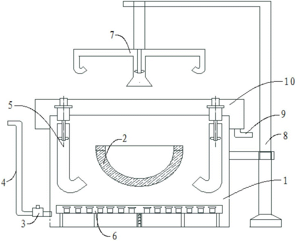
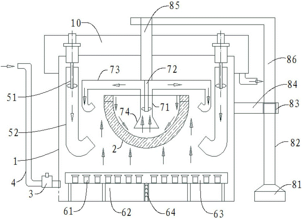
[0023] refer to Figure 1-2 As shown, the quenching and cooling device of the large head of the present invention includes a tank body 1, the head 2 is placed inside the tank body 1, the tank body 1 is connected with a cooling medium pipeline 4 through a drive pump 3, and the cooling medium pipe Road 4 is provided with a cooling medium, which also includes:

[0024] The propeller agitating jet device 5 is arranged in the circumferential direction of the inner wall of the tank body 1, and the propeller agitating jet device 5 is used to form a jet of the cooling medium in the upper part of the tank body 1 and spray it onto the outer side wall of th...


PUM


Abstract

The invention discloses a quenching cooling device for a large seal head. The quenching cooling device comprises a groove body. The seal head is placed in the groove body. The groove body is connected with a cooling medium pipeline through a driving pump. A cooling medium is arranged in the cooling medium pipeline. The quenching cooling device further comprises a propeller stirring jet device, a diving stirring jet device, a centrifugal pump water pumping device and a position adjusting device. According to the quenching cooling device, the propeller stirring jet device, the diving stirring jet device and the centrifugal pump water pumping device are arranged in different positions in the groove body, thus district cooling of the outer wall, the inner wall and other areas of the seal head is achieved, and overall circular flowing of the cooling medium in the groove body is also achieved. Therefore, the quenching cooling device can effectively ensure the quenching quality of the seal head, the utilization ratio of the cooling medium is improved, the structure is simple, and the practical operability is high.

Description

technical field [0001] The invention relates to the technical field of quenching and cooling devices, in particular to a quenching and cooling device for large-scale heads. Background technique [0002] Quenching is a heat treatment process used to obtain the expected structure and properties of the workpiece. In order to ensure the quality of quenching, it is necessary to ensure that the surrounding cooling medium on each surface of the workpiece has a sufficient and uniform flow rate during quenching. If the flow rate of the cooling medium is too low, the cooling rate of the workpiece will be low, and the required structure and performance of the workpiece cannot be obtained; the flow rate of the cooling medium around each surface of the workpiece or different areas of a certain surface of the workpiece is uneven, and the cooling rate of different positions on the surface of the workpiece will be different. Even, it is easy to cause uneven hardness on the surface of the w...

Claims


Application Information

Patent Timeline
IPC IPC(8): C21D9/00C21D1/64
CPCC21D1/64C21D9/0062C21D9/0068
Inventor 孙会郅东东马雪芬沈忱
Owner SHANGHAI DIANJI UNIV
Why Eureka
Try Eureka