A pair of locking device

A mortise lock and mounting seat technology, applied in the direction of mechanical equipment, connecting components, etc., can solve the problems of rigid impact, cannot be locked at the same time, complex structure, etc., to prevent the rise of the stroke from exceeding the limit, the bearing load range is large, and the quality of personnel is achieved. less demanding effects

Active Publication Date: 2019-07-19
CHENGDU SIYUAN BROTHER SCI & TECH CO LTD
View PDF8 Cites 0 Cited by
  • Summary
  • Abstract
  • Description
  • Claims
  • Application Information

AI Technical Summary

Problems solved by technology

Common locking mechanisms are mainly divided into two types: rigid and flexible: some rigid locks are hooked and separated by rigid hooks, or rigid structures are used to forcibly pull or insert for alignment, and such locks will produce rigid shocks when used , it will cause some damage to the structure, and there are often failures to mount or separate
When multiple sets of locks are used at the same time, it often happens that they cannot be locked at the same time. When the outdoor wind load is large, it will shake or even decouple, which is a great safety hazard. Therefore, the installation and maintenance process requires high quality personnel, and the service life of the lock mechanism is short; Most of the common flexible locks are connected with complex and precise floating mechanisms to ensure that the locks can be docked smoothly. When separating, spring reset or complex ratchet mechanisms are used to separate. Although this type of lock mechanism avoids rigid impact, the lock and The separation is more reliable and the service life is prolonged, but the flexible locking mechanism is mostly a precision mechanism with a complex structure and a large shape, which is not suitable for equipment with large outdoor pollution and limited installation space, and is not suitable for occasions with large loads

Method used


Image

  • A pair of locking device
  • A pair of locking device
  • A pair of locking device

Examples


Embodiment

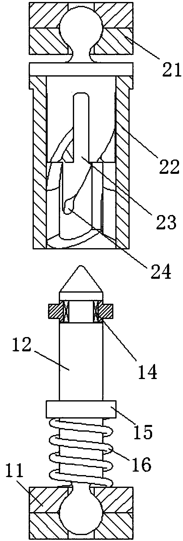
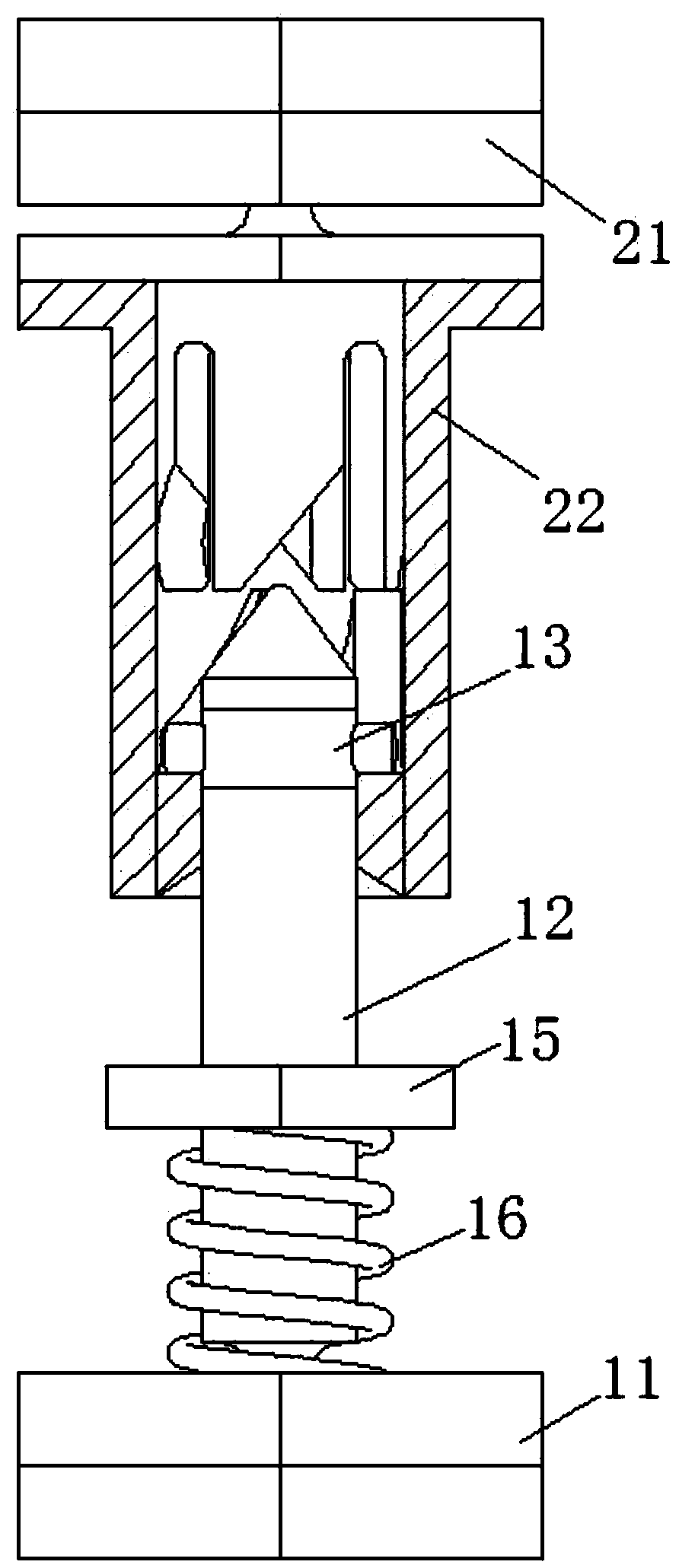
[0023] Example: see Figure 1 to Figure 7 , an anti-mortise locking device, comprising a first mounting seat 11 on which a male head 12 is arranged, and the bottom of the male head 12 is assembled with the first mounting seat 11 to form a spherical pair, the The lower part of the male head 12 is provided with a support structure for keeping the male head in an upright state, the upper part of the male head 12 is provided with a rotating sleeve 13 , the rotating sleeve 13 is connected with the male head 12 through a one-way bearing 14 , and the outside of the rotating sleeve 13 is Set the pin.

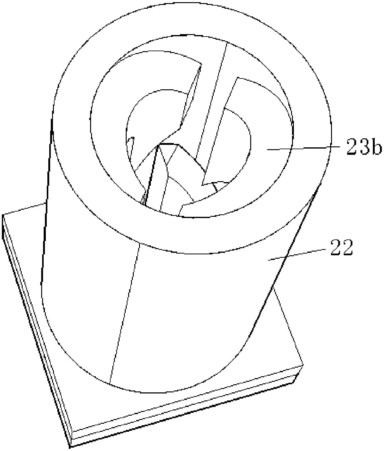
[0024] A female header 22 is arranged under the second mounting seat 21 , the top of the female header 22 is assembled with the second mounting seat 21 to form a spherical pair, a guide groove structure 23 is arranged in the female header 22 , and a lock is arranged at the guide groove structure 23 The notch 24 is tightened, and the locking notch cooperates with the pin to lock the pos...


PUM


Abstract

The invention discloses an opposite insertion locking device which comprises a first mounting base, wherein a male head is arranged on the first mounting base; the bottom of the male head and the first mounting base are assembled to form a spherical pair; a support structure capable of keeping the male head in a vertical state is arranged at the lower part of the male head; a rotary sleeve is arranged at the upper part of the male head and is connected with the male head through a one-way bearing; a pin shaft is arranged out of the rotary shaft; a female head is arranged below a second mounting base; the top of the female head and the second mounting base are assembled to form another spherical pair; a guide groove structure is arranged in the female head; a locking notch is formed in the guide groove structure; and the locking notch and the pin shaft are matched for locking. The opposite insertion locking device is simple in structure, convenient to use and better in stability.

Description

technical field [0001] The present invention relates to a locking device, in particular to a locking device for insertion. Background technique [0002] The locking mechanism is used to enable the device to be locked in a fixed position after running for a certain distance, and it can be separated smoothly or automatically reset when it needs to be disengaged. Common locking mechanisms are mainly divided into two categories: rigid and flexible: some rigid locks use rigid hooks to connect and separate, or use rigid structures to forcibly pull or insert them for alignment. Such locks will produce rigid shocks when used. , which will cause certain damage to the structure, and often fail to attach or detach. When multiple sets of locks are used at the same time, the phenomenon that they cannot be locked at the same time often occurs. When the outdoor wind load is large, there will be shaking or even decoupling, and the safety hazard is large. Therefore, the installation and mai...

Claims


Application Information

Patent Timeline
Patent Type & Authority Patents(China)
IPC IPC(8): F16B21/02
CPCF16B21/02
Inventor 郭聪杨翼宾
Owner CHENGDU SIYUAN BROTHER SCI & TECH CO LTD
Why Eureka
Try Eureka