
Ceramic valve element with drinking water control function

A ceramic spool and functional technology, applied in the direction of valve devices, multi-way valves, mechanical equipment, etc., can solve the problems of faucet structure complexity, inconvenient use process, high cost of use, and achieve low cost, avoid pollution, and easy installation Effect

Inactive Publication Date: 2017-05-24
SHANGHAI GEAR PLASTIC
View PDF6 Cites 5 Cited by
  • Summary
  • Abstract
  • Description
  • Claims
  • Application Information

AI Technical Summary

Problems solved by technology

[0002] Press, the use of the faucet is mainly to use the ceramic spool to provide operation through the handle, and can achieve the conversion of turning on and off the water or changing the mixing ratio of cold and hot water and the size of the water flow, but because the existing ceramic spool can only provide one When using the water flow mode, it is like when there are two kinds of water outlets with different functions on the same faucet (if you need to have tap water and filtered drinking water at the same time, the tap water must also have the mixing function of cold and hot water), you need Adding another ceramic valve core to the faucet will greatly increase the structural complexity of the entire faucet, and the cost of use will also be higher. When using water, the hand needs to move between the two ceramic valve cores. , so that the whole use process will be more inconvenient and troublesome

Method used


Image

  • Ceramic valve element with drinking water control function
  • Ceramic valve element with drinking water control function
  • Ceramic valve element with drinking water control function

Examples


Embodiment Construction

[0050] The present invention will be further described below in conjunction with the accompanying drawings and specific embodiments, so that those skilled in the art can better understand the present invention and implement it, but the examples given are not intended to limit the present invention.

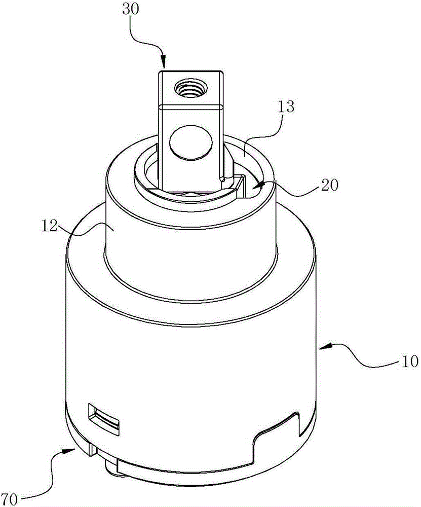
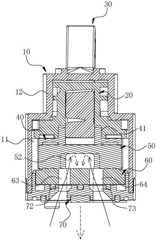
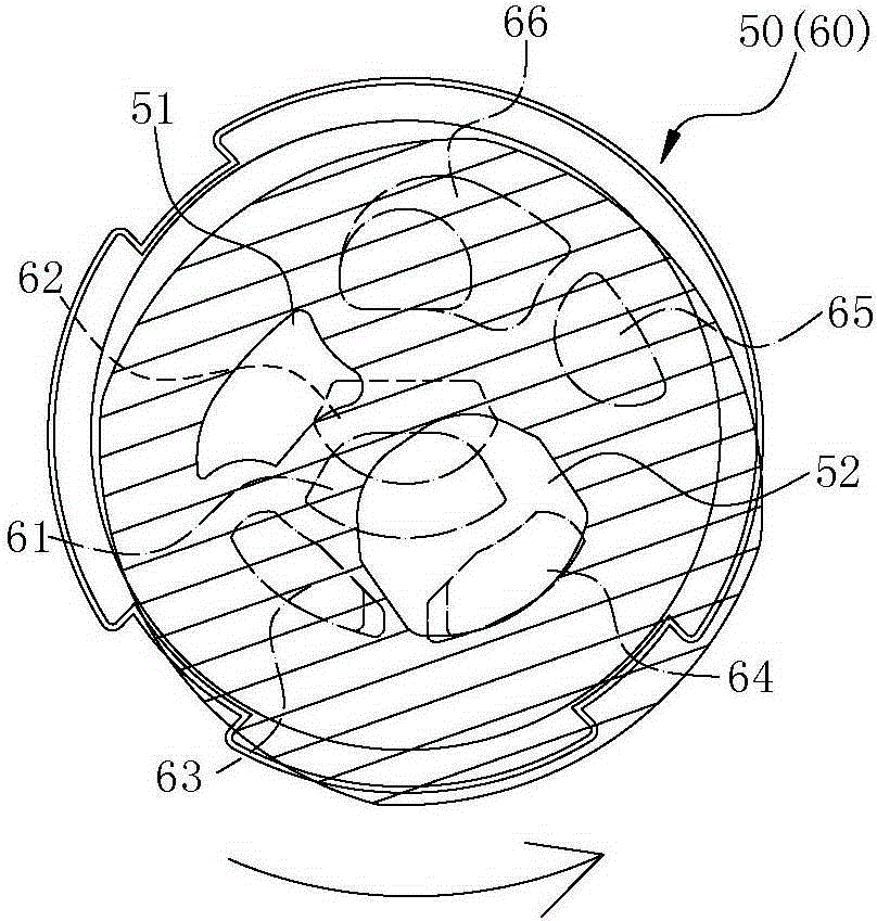
[0051] Usually according to the present invention, please firstly by Figure 1 to Figure 6As shown, the ceramic valve core of the present invention is provided with a rotating seat 20 in a valve casing 10, and a connecting block 40, a movable valve plate 50 and a fixed valve plate 50 are arranged in sequence below the rotating seat 20. The valve plate 60 and the rotating seat 20 have a valve stem 30 protruding upward from the valve housing 10 in the central group. The valve plate 50 will be able to drive the movable valve plate 50 to translate or rotate through the linkage block 40 through the operation of the valve stem 30, so as to use the change of the alignment relationship be...


PUM


Abstract

The invention discloses a ceramic valve element with a drinking water control function. The ceramic valve element is formed in the manner that a rotating base is arranged in a valve shell in an assembled manner, a linking block, a movable valve block and a fixed valve block which are sequentially overlapped are arranged below the rotating base, a valve rod upwards extending out of the valve shell is arranged in the rotating base in pivoted manner, a stirring part at the bottom end of the valve rod and the linking block are embedded, the movable valve block is embedded through the linking block, and the movable valve block is driven by the linking block to move horizontally or rotate through the operation of the valve rod; by means of the change of the position corresponding relation between the movable valve block and the fixed valve block, a tap is controlled to allow water to flow or stop water flowing, or the mixing proportion of cold water and hot water and the output water flow are changed, and internal members such as the fixed valve block, the movable valve block, the linking block and the rotating base are stopped from dropping out through combination of a valve seat below the valve shell. The ceramic valve element can control use of tap water and drinking water, and the complexity of the whole structure is effectively simplified.

Description

technical field [0001] The present invention relates to a "ceramic valve core with the function of controlling drinking water", especially a ceramic valve core that uses the change of the alignment relationship of the internal valve plate to control the opening and closing of cold, hot water and drinking water structure. Background technique [0002] Press, the use of the faucet is mainly to use the ceramic spool to provide operation through the handle, and can achieve the conversion of turning on and off the water or changing the mixing ratio of cold and hot water and the size of the water flow, but because the existing ceramic spool can only provide one When using the water flow mode, it is like when there are two kinds of water outlets with different functions on the same faucet (if you need to have tap water and filtered drinking water at the same time, the tap water must also have the mixing function of cold and hot water), you need Adding another ceramic valve core to...

Claims


Application Information

Patent Timeline
IPC IPC(8): F16K11/074
CPCF16K11/074
Inventor 杨建弘
Owner SHANGHAI GEAR PLASTIC
Features
  • Generate Ideas
  • Intellectual Property
  • Life Sciences
  • Materials
  • Tech Scout
  • Unparalleled Data Quality
  • Higher Quality Content
  • 60% Fewer Hallucinations
Learn More