
Miniature probe illuminometer

An illuminance meter and lens technology, applied in the field of illuminance measurement devices, can solve the problems of complex structure, the size of the illuminance probe cannot be placed in a narrow space, and the demand for illuminance measurement cannot be directly performed, etc., and achieves the effect of miniaturization and compact mechanical structure design.

Inactive Publication Date: 2017-05-24
SOUTH CHINA UNIV OF TECH
View PDF5 Cites 0 Cited by
  • Summary
  • Abstract
  • Description
  • Claims
  • Application Information

AI Technical Summary

Problems solved by technology

The illuminance measurement probe of a common illuminance meter is not only complex in structure, but also contains components such as photoelectric sensors. Therefore, the size of the illuminance probe is too large to be placed in a small space, making it impossible to directly perform such illuminance measurement requirements.

Method used


Image

  • Miniature probe illuminometer

Examples


Embodiment

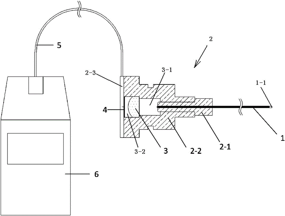
[0024] Such as figure 1 shown. The invention discloses a micro-probe illuminance meter. The micro-probe illuminance meter sequentially includes an optical fiber 1, a lens 3 and a photoelectric sensor 4 according to the optical signal transmission path;

[0025] The optical fiber 1 , the lens 3 and the photoelectric sensor 4 are axially and sequentially fixed inside the fixing assembly 2 according to the optical signal transmission path. The lens 3 is used to diverge the light guided by the optical fiber into parallel light.

[0026] The fixing assembly 2 sequentially includes a first sleeve 2-1, a second sleeve 2-2 and a sealing end cap 2-3; socket connection;

[0027] The second sleeve 2-2 sequentially includes an isolation cavity 3-1 and a lens cavity 3-2 according to the optical signal transmission path; the end of the optical fiber 1 is placed and fixed in the first sleeve 2-1;

[0028] The lens 3 is placed and fixed in the lens chamber 3-2 of the second sleeve 2-2;

...


PUM


Abstract

The present invention discloses a miniature probe illuminometer. The miniature probe illuminometer comprises fibers, a lens and a photoelectric sensor according to an optical signal transmission path. The fibers, the lens and the photoelectric sensor are fixed within a fixed component along the axial direction according to the optical signal transmission path. The illuminometer can directly realize the luminance test in a narrow space. The optical conduction design is employed to separate the photoelectric sensor and a fine fiber-optics probe to allow a measured light ray to be subjected to conduction of the fibers and divergence of the lens to enter the photoelectric sensor so as to output electric signals to output an illuminance value. The probe end of the fiber is only the size of the section of the fibers, the measured light ray is conducted through fibers to the lens and is subjected to divergence of the lens to enter the photoelectric sensor, the photoelectric sensor outputs electric signals, the electric signals are transmitted to the illuminometer host through wires, and the illuminometer host displays and outputs the illuminance value.

Description

technical field [0001] The invention relates to an illumination measuring device, in particular to a micro-probe illumination meter. Background technique [0002] The measurement of illuminance is a basic light parameter measurement, which has a wide range of needs. It is necessary to develop different types of illuminance meters suitable for different measurement conditions. In many cases involving illuminance measurement in a small space has become an urgent problem to be solved. The illuminance measurement probe of a common illuminance meter is not only complex in structure, but also contains components such as photoelectric sensors. Therefore, the illuminance probe is too large to be placed in a narrow space, making this type of illuminance measurement requirements impossible to perform directly. Contents of the invention [0003] The object of the present invention is to overcome the shortcomings and deficiencies of the above-mentioned prior art, and provide a micro-...

Claims


Application Information

Patent Timeline
Patent Type & Authority Applications(China)
IPC IPC(8): G01J1/42G01J1/04
CPCG01J1/42G01J1/0425
Inventor 边宇马源
Owner SOUTH CHINA UNIV OF TECH
Learn More