
Optocoupler current detection circuit

A technology of current detection circuit and current detection unit, which is applied in the direction of voltage/current isolation, etc., can solve problems such as poor stability and drift, and achieve the effect of strong stability, good stability, and accurate detection results

Pending Publication Date: 2017-05-24
HUIZHOU SANHUA IND
View PDF5 Cites 3 Cited by
  • Summary
  • Abstract
  • Description
  • Claims
  • Application Information

AI Technical Summary

Problems solved by technology

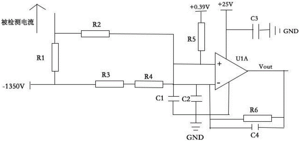
However, because of the high-value resistors, when the power supply works for a long time and in a high-temperature and high-humidity environment, the resistance of the high-value resistors has poor stability in harsh environments due to the process. If the change range of the sampling resistors R1 and R2 is the same as When the amplitudes of the sampling resistors R3 and R4 are inconsistent, the voltage of the detection result Vout output by the operational amplifier is also likely to drift on the original basis

Method used


Image

  • Optocoupler current detection circuit
  • Optocoupler current detection circuit
  • Optocoupler current detection circuit

Examples


Embodiment Construction

[0033] In order to facilitate the understanding of the present invention, the present invention will be described more fully below with reference to the associated drawings. Preferred embodiments of the invention are shown in the accompanying drawings. However, the present invention can be embodied in many different forms and is not limited to the embodiments described herein. On the contrary, the purpose of providing these embodiments is to make the disclosure of the present invention more thorough and comprehensive.

[0034] It should be noted that when an element is referred to as being “fixed” to another element, it can be directly on the other element or there can also be an intervening element. When an element is referred to as being "connected to" another element, it can be directly connected to the other element or intervening elements may also be present. The terms "vertical," "horizontal," "left," "right," and similar expressions are used herein for purposes of ill...


PUM


Abstract

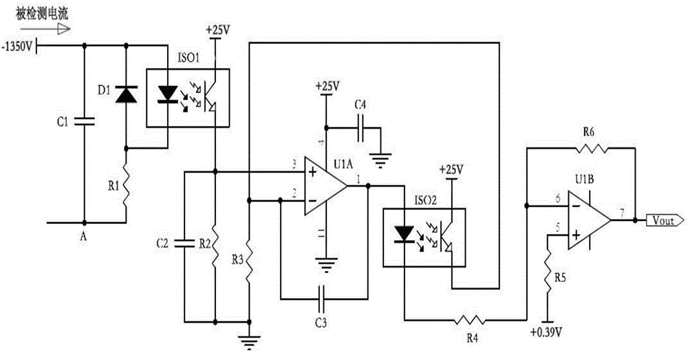
The present invention discloses an optocoupler current detection circuit. The optocoupler current detection circuit comprises a current detection unit, an optocoupler negative feedback unit and a reverse amplification unit; the input end of the current detection unit is adopted as the input end of the optocoupler current detection circuit; the output end of the reverse amplification unit is adopted as the output end of the optocoupler current detection circuit; and the current detection unit, the optocoupler negative feedback unit and the reverse amplification unit are connected with one another sequentially. According to the optocoupler current detection circuit provided by the technical schemes of the invention, an optocoupler is adopted in the current detection unit, so that the application of a high-resistance resistor is avoided, and therefore, the accuracy of the detection of the circuit will not be affected by the instability of the high-resistance resistor when the circuit is used under high-temperature high-humidity harsh environments; and an optocoupler can be adopted to constitute the negative feedback circuit so as to play the role of automatic adjustment, and detection results can be stable and balanced.

Description

technical field [0001] The invention relates to the field of current detection, in particular to an optocoupler current detection circuit. Background technique [0002] In the laser printer system, it is usually necessary to detect the output current of the high-voltage power supply to adjust the required analog signal. Because it is to detect the output current in the high-voltage circuit, if a differential current detection circuit is used, then the positive-phase and negative-phase output terminals of the differential operational amplifier will inevitably use high-value resistors to limit its positive-phase and negative-phase output. The input current at the terminal obtains a smaller output voltage signal at the same time, and the higher the voltage connected to the detection point, the larger the resistance value required. However, the resistance value of high-value resistors will change after a long time in a high-temperature and high-humidity environment. If the tem...

Claims


Application Information

Patent Timeline
IPC IPC(8): G01R15/24
CPCG01R15/24
Inventor 黎志勇张世桐李坚林儿
Owner HUIZHOU SANHUA IND
Learn More