
Display panel and display device

A technology for display panels and row pixels, applied in static indicators, instruments, semiconductor devices, etc., can solve problems such as poor display effect and panel charging time squeeze, and achieve good display effect and good application effect.

Active Publication Date: 2019-04-23
XIAMEN TIANMA MICRO ELECTRONICS
View PDF8 Cites 0 Cited by
  • Summary
  • Abstract
  • Description
  • Claims
  • Application Information

AI Technical Summary

Problems solved by technology

[0004] When the display panel is used in virtual reality or augmented reality, usually the left and right eyes of the display have different visual areas. In order to improve the visual effect, it is usually necessary to increase the refresh rate of the display panel to 120HZ. After the refresh rate is increased, the charging time of the panel is obviously squeezed. The display effect is not good, especially as the resolution of the display panel is getting higher and higher, the charging time becomes the key to improving the display effect of the display panel

Method used


Image

  • Display panel and display device
  • Display panel and display device
  • Display panel and display device

Examples


Embodiment Construction

[0016] The present invention will be further described in detail below in conjunction with the accompanying drawings and embodiments. It should be understood that the specific embodiments described here are only used to explain the present invention, but not to limit the present invention. In addition, it should be noted that, for the convenience of description, only some structures related to the present invention are shown in the drawings but not all structures. And for a clearer description, the same reference numerals are used between different drawings.

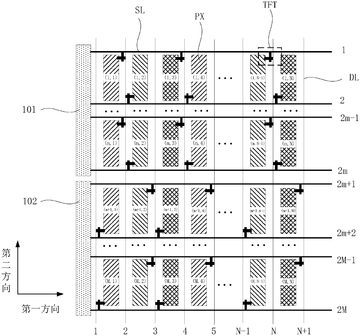
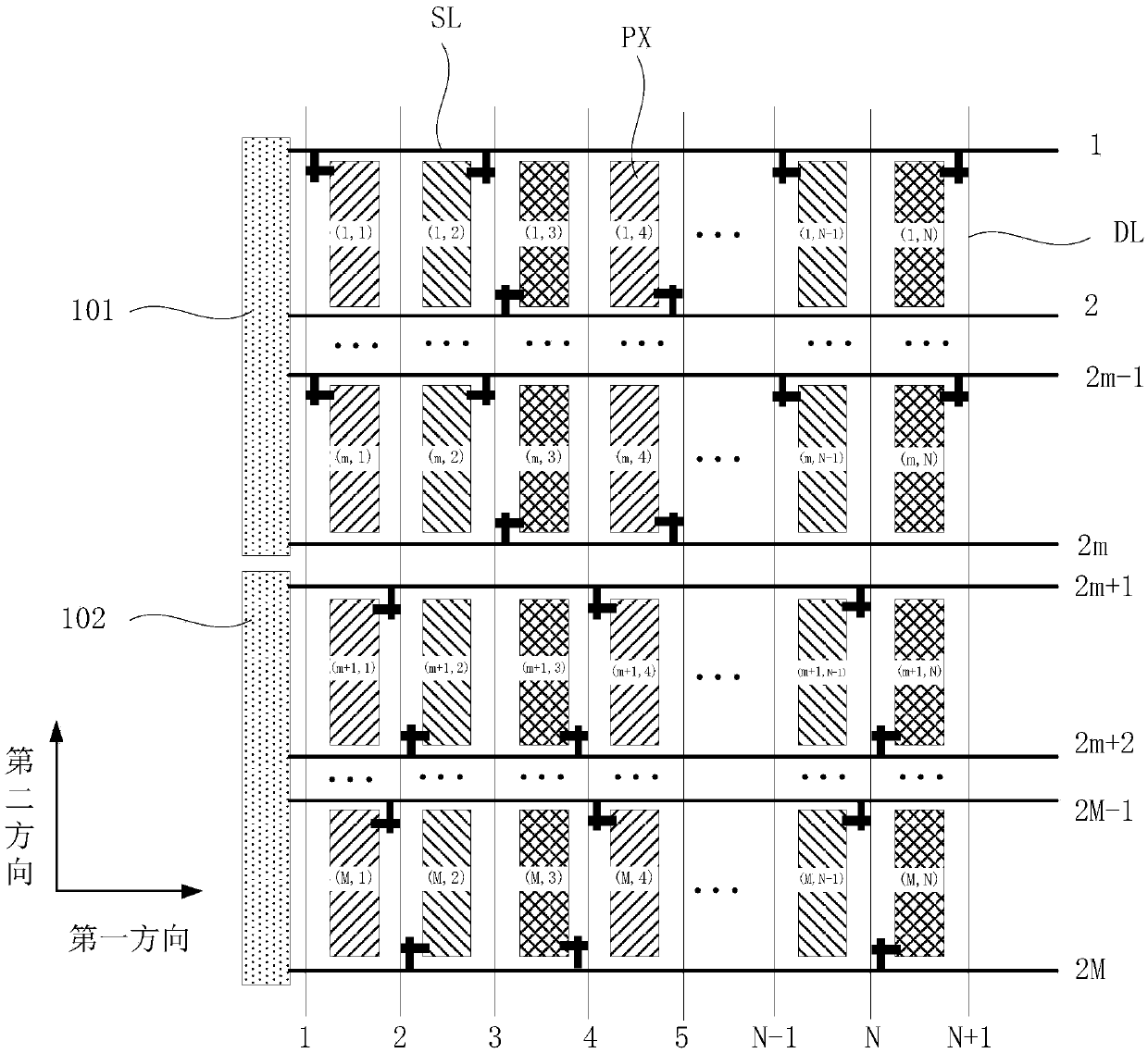
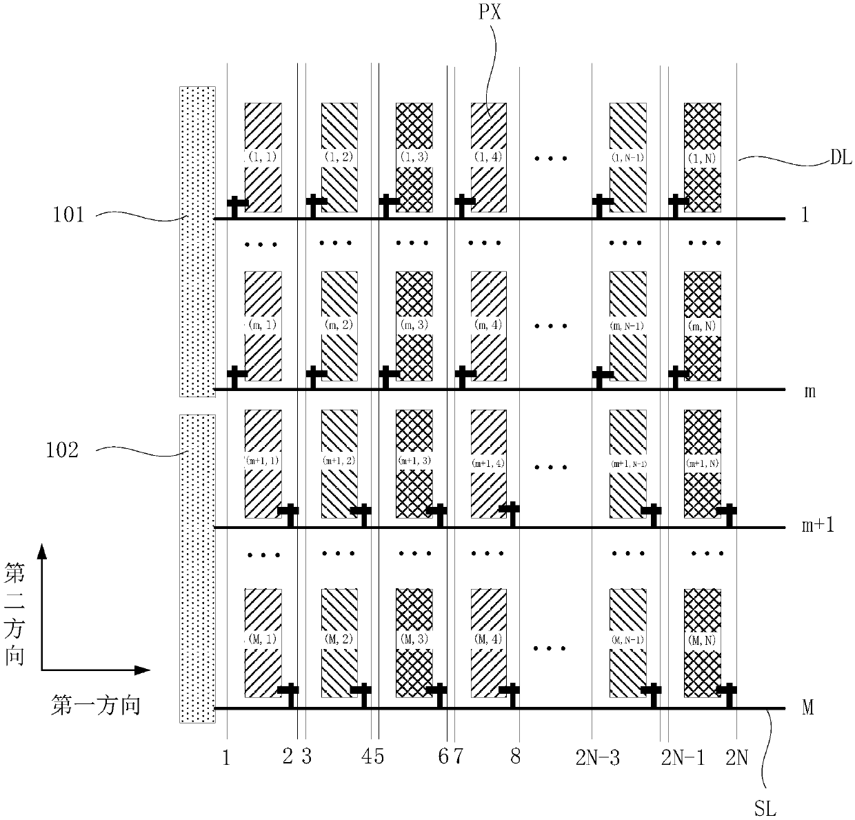
[0017] figure 1 A schematic diagram of a display panel provided for an embodiment of the present invention, such as figure 1 As shown, the display panel includes gate lines SL and data lines DL. The gate lines extend along the row direction and are arranged along the column direction. The data lines extend along the column direction and are arranged along the row direction. The gate lines and the Pixel units are arran...


PUM


Abstract

The invention provides a display panel, comprising: gate lines and data lines, the gate lines extend along the row direction and are arranged along the column direction, the data lines extend along the column direction and are arranged along the row direction, the gate lines and the data lines Pixel units are arranged in the area defined by the intersection of the lines, and the pixel units are arranged in an array of M rows and N columns; the first gate driver and the second gate driver, the pixel units from the first row to the mth row are connected to the first gate driver, The pixel unit in the m+1th row to the Mth row is connected to the second gate driver; for any pixel unit in the nth column, the first row to the nth column, the mth row, the pixel unit is connected to the integrated circuit through a data line, and the nth column The pixel units in the m+1 to the nth column and the Mth row are connected to the integrated circuit through another data line; where M, N, m, and n are positive integers, and, 1

Description

technical field [0001] The present invention relates to the display field, in particular to a display panel and a display device. Background technique [0002] The current common flat-panel displays usually include a liquid crystal display panel and an organic light-emitting diode display panel. No matter which display panel has an array substrate for driving pixel units to emit light, gate lines and gates for providing scanning signals are formed on the array substrate. The vertical data line is used to provide the data signal. A pixel unit is defined between the gate line 11 and the data line. The pixel unit is provided with a thin film transistor (ThinFilm Transistor, TFT) and a pixel electrode. The gate and gate of the thin film transistor Line connection, source and data line connection, drain and pixel electrode connection. [0003] When the display panel is working, the gate lines are controlled by the gate driver, and the data lines are controlled by the source driv...

Claims


Application Information

Patent Timeline
Patent Type & Authority Patents(China)
IPC IPC(8): G09G3/36G09G3/3225
CPCG09G3/3225G09G3/3648G09G2310/0205G09G2310/0218G09G2310/0221G09G3/3266G09G3/3677G09G2300/0426H10K59/121G09G3/2092G09G2310/08
Inventor 杨康鹏许育民郑超刘少凡陈晓梦
Owner XIAMEN TIANMA MICRO ELECTRONICS
Learn More