A spacer for nuclear fuel assemblies

A technology for nuclear fuel components and positioning grids, which is applied in the assembly of fuel elements, reactor fuel elements, nuclear engineering, etc. It can solve the problems of increasing the hooking of strips outside the positioning grids, so as to reduce the risk of hooking and reduce the hydraulic force. Reduced effect

Active Publication Date: 2018-04-24
NUCLEAR POWER INSTITUTE OF CHINA
View PDF5 Cites 0 Cited by
  • Summary
  • Abstract
  • Description
  • Claims
  • Application Information

AI Technical Summary

Problems solved by technology

[0005] Aiming at the problem in the above-mentioned prior art that the deformation of the positioning grid caused by the above hydraulic force will also increase the risk of hooking the strips outside the positioning grid due to the hydraulic influence generated during the working process of the guide wing and the mixing wing, the present invention Provided is a spacer grid for nuclear fuel assemblies, the spacer grid can effectively relieve the hydraulic force borne by the outer strips to reduce the deformation of the outer strips, thereby achieving the effect of reducing the risk of the spacer grid being hooked

Method used


Image

  • A spacer for nuclear fuel assemblies
  • A spacer for nuclear fuel assemblies
  • A spacer for nuclear fuel assemblies

Examples


Embodiment 1

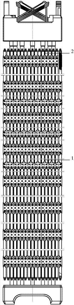
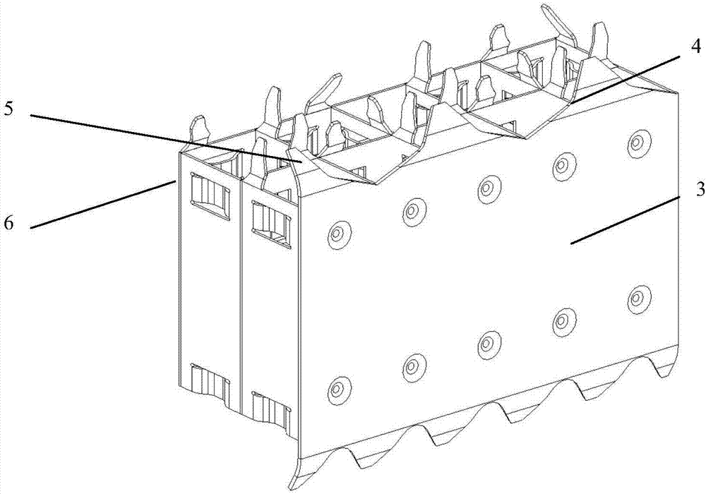
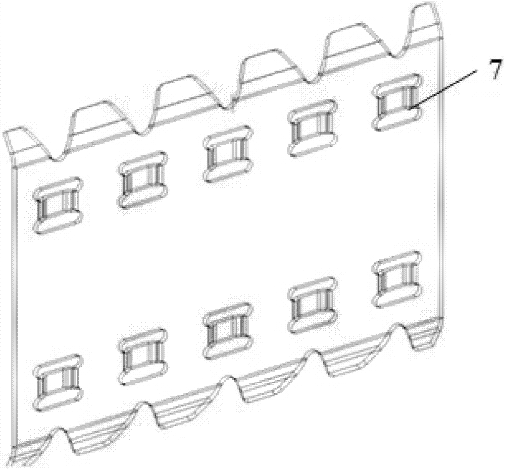
[0021] Such as Figure 1 to Figure 3 As shown, a spacer grid for nuclear fuel assemblies includes an outer strip, the upper end of the outer strip is also provided with a guide wing 4, and also includes a through hole 7 arranged at the upper end of the outer strip, and the through hole 7 run through the inside and outside of the outer strap.

[0022] Specifically, the positioning grid in the prior art includes a structural mixing grid 1 and an end grid 2, and the positioning grid includes an outer strip 3 located on the outside and an inner strip 5 arranged on the inner side of the outer strip 3, so The outer strip 3 is used as the outer edge of the positioning grid, and the inner strip 5 divides the middle part of the positioning grid into lattice shapes. Generally, guide wings 4 are set on the upper and lower sides of the positioning grid as required, The upper side of the frame is provided with mixing wings 6.

[0023] In this scheme, the through hole 7 arranged at the up...

Embodiment 2

[0025] The present embodiment is further limited on the basis of embodiment 1, as Figure 1 to Figure 3 As shown, since the fluid flow direction inside and outside the spacer is from bottom to top, as a technical solution to reduce the hydraulic pressure difference between the inside and outside of the outer strip 3 at the initial position when the fluid flows through the spacer , the lower end of the outer strip is provided with a through hole 7 . Simultaneously, the through hole 7 that is arranged on the lower edge of the outer strip 3 in this program is owing to be positioned at the edge of the outer strip 3, like this, the position selection of the through hole 7 on the outer strip 3 has little influence on the rigidity of the outer strip 3.

Embodiment 3

[0027] This embodiment further limits this case on the basis of any one of the technical solutions provided by any one of the above embodiments: Figure 1 to Figure 3 As shown, in order to facilitate the rigidity of the positioning grid, as a technical solution that can use the rigid convex outer strip 3 to open holes and reinforce, the outer strip is also provided with rigid convex, and the through hole 7 is located around the rigid convex Or lie on just convex. Further, since the rigid projections are used to complete the rigid abutment of the fuel rods in the positioning grid, the position of the through hole 7 is limited around the rigid projections or on the rigid projections, which can effectively accelerate the rigid projections and the fuel rods. In this way, the stress corrosion in the corresponding area of ​​the spacer grid can be effectively relieved.

[0028] As a technical solution along the circumferential direction of the through holes 7, it is preferable to us...


PUM


Abstract

The invention discloses a positioning grid for nuclear fuel assemblies, which comprises an outer strip, the upper end of the outer strip is provided with a guide wing, and a through hole arranged at the upper end of the outer strip, and the through hole runs through the The inside and outside of the outer strap. The spacer grid can effectively alleviate the hydraulic force borne by the outer strips to reduce the deformation of the outer strips, thereby achieving the effect of reducing the risk of the spacer grid being hooked.

Description

technical field [0001] The invention relates to the technical field of fuel assemblies, in particular to a positioning grid for nuclear fuel assemblies. Background technique [0002] A certain number of fuel rods are arranged at certain intervals (such as: 15×15 or 17×17, etc.) and fixed into a bundle, plus various structural parts, called reactor fuel assemblies, which are mainly composed of tube sockets, It consists of upper and lower tube bases, positioning grids, guide tubes and fuel rods. Generally, reactor fuel assemblies are used in nuclear reactors for 3-5 years. Because they are in a strong neutron field, they need to withstand high temperature, high pressure, and high flow rate coolants, and at the same time they need to withstand the chemical action of fission products and complex mechanical loads. Therefore, the working conditions are very harsh. [0003] Chain reaction velocity and temperature are important control parameters for nuclear reactors, so flow cont...

Claims


Application Information

Patent Timeline
Patent Type & Authority Patents(China)
IPC IPC(8): G21C3/34
CPCG21C3/3424Y02E30/30
Inventor 陈杰陈平雷涛彭园焦拥军李庆肖忠
Owner NUCLEAR POWER INSTITUTE OF CHINA
Why Eureka
Try Eureka