Positioning grillwork for nuclear fuel assembly
A technology for nuclear fuel components and positioning grids, which is applied in the assembly of fuel elements, reactor fuel elements, nuclear engineering, etc. It can solve the problems of increasing the hooking of strips outside the positioning grids, so as to reduce the risk of hooking and reduce the hydraulic force. Reduced effect
- Summary
- Abstract
- Description
- Claims
- Application Information
AI Technical Summary
Problems solved by technology
Method used
Image
Examples
Embodiment 1
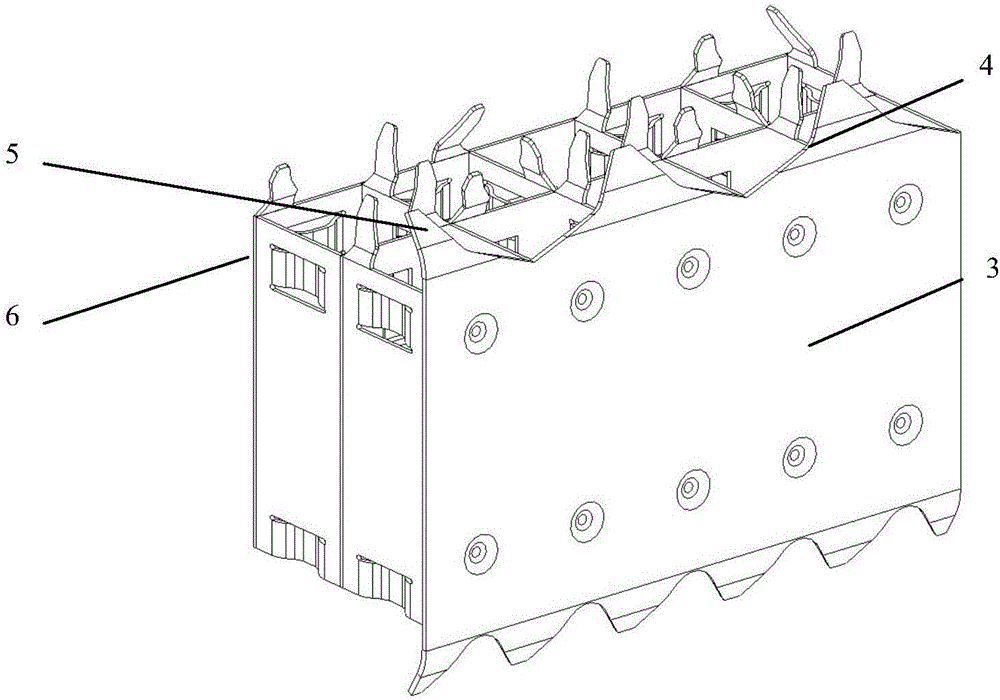
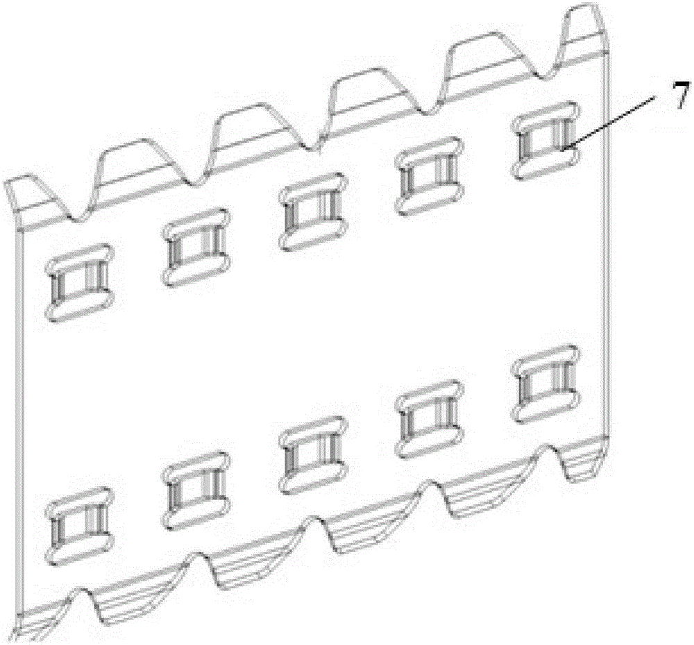
[0021] Such as Figure 1 to Figure 3 As shown, a spacer grid for nuclear fuel assemblies includes an outer strip, the upper end of the outer strip is also provided with a guide wing 4, and also includes a through hole 7 arranged at the upper end of the outer strip, and the through hole 7 run through the inside and outside of the outer strap.
[0022] Specifically, the positioning grid in the prior art includes a structural mixing grid 1 and an end grid 2, and the positioning grid includes an outer strip 3 located on the outside and an inner strip 5 arranged on the inner side of the outer strip 3, so The outer strip 3 is used as the outer edge of the positioning grid, and the inner strip 5 divides the middle part of the positioning grid into lattice shapes. Generally, guide wings 4 are set on the upper and lower sides of the positioning grid as required, The upper side of the frame is provided with mixing wings 6.
[0023] In this scheme, the through hole 7 arranged at the up...
Embodiment 2
[0025] The present embodiment is further limited on the basis of embodiment 1, as Figure 1 to Figure 3 As shown, since the fluid flow direction inside and outside the spacer is from bottom to top, as a technical solution to reduce the hydraulic pressure difference between the inside and outside of the outer strip 3 at the initial position when the fluid flows through the spacer , the lower end of the outer strip is provided with a through hole 7 . Simultaneously, the through hole 7 that is arranged on the lower edge of the outer strip 3 in this program is owing to be positioned at the edge of the outer strip 3, like this, the position selection of the through hole 7 on the outer strip 3 has little influence on the rigidity of the outer strip 3.
Embodiment 3
[0027] This embodiment further limits this case on the basis of any one of the technical solutions provided by any of the above embodiments: Figure 1 to Figure 3 As shown, in order to facilitate the rigidity of the positioning grid, as a technical solution that can use the rigid convex outer strip 3 to open holes and reinforce, the outer strip is also provided with rigid convex, and the through hole 7 is located around the rigid convex Or lie on just convex. Further, since the rigid projections are used to complete the rigid abutment of the fuel rods in the positioning grid, the position of the through hole 7 is limited around the rigid projections or on the rigid projections, which can effectively accelerate the rigid projections and the fuel rods. In this way, the stress corrosion in the corresponding area of the spacer grid can be effectively relieved.
[0028] As a technical solution along the circumferential direction of the through holes 7, it is preferable to use ri...
PUM
 Abstract
Description
Claims
Application Information
 - R&D
- Intellectual Property
- Life Sciences
- Materials
- Tech Scout
- Unparalleled Data Quality
- Higher Quality Content
- 60% Fewer Hallucinations
Browse by: Latest US Patents, China's latest patents, Technical Efficacy Thesaurus, Application Domain, Technology Topic, Popular Technical Reports.
© 2025 PatSnap. All rights reserved.Legal|Privacy policy|Modern Slavery Act Transparency Statement|Sitemap|About US| Contact US: help@patsnap.com


