Electromagnetic actuator and electrical contactor including such actuator

A technology of electromagnetic actuators and electrical contactors, applied in electromagnetic relays, electromagnetic relay details, relays, etc., can solve problems such as weakening the impact resistance of actuators, and achieve the effect of increasing electromagnetic force

Active Publication Date: 2020-05-15
SCHNEIDER ELECTRIC IND SAS
View PDF4 Cites 0 Cited by
  • Summary
  • Abstract
  • Description
  • Claims
  • Application Information

AI Technical Summary

Problems solved by technology

This weakens the impact resistance of the actuator, which is unacceptable

Method used


Image

  • Electromagnetic actuator and electrical contactor including such actuator
  • Electromagnetic actuator and electrical contactor including such actuator
  • Electromagnetic actuator and electrical contactor including such actuator

Examples


Embodiment Construction

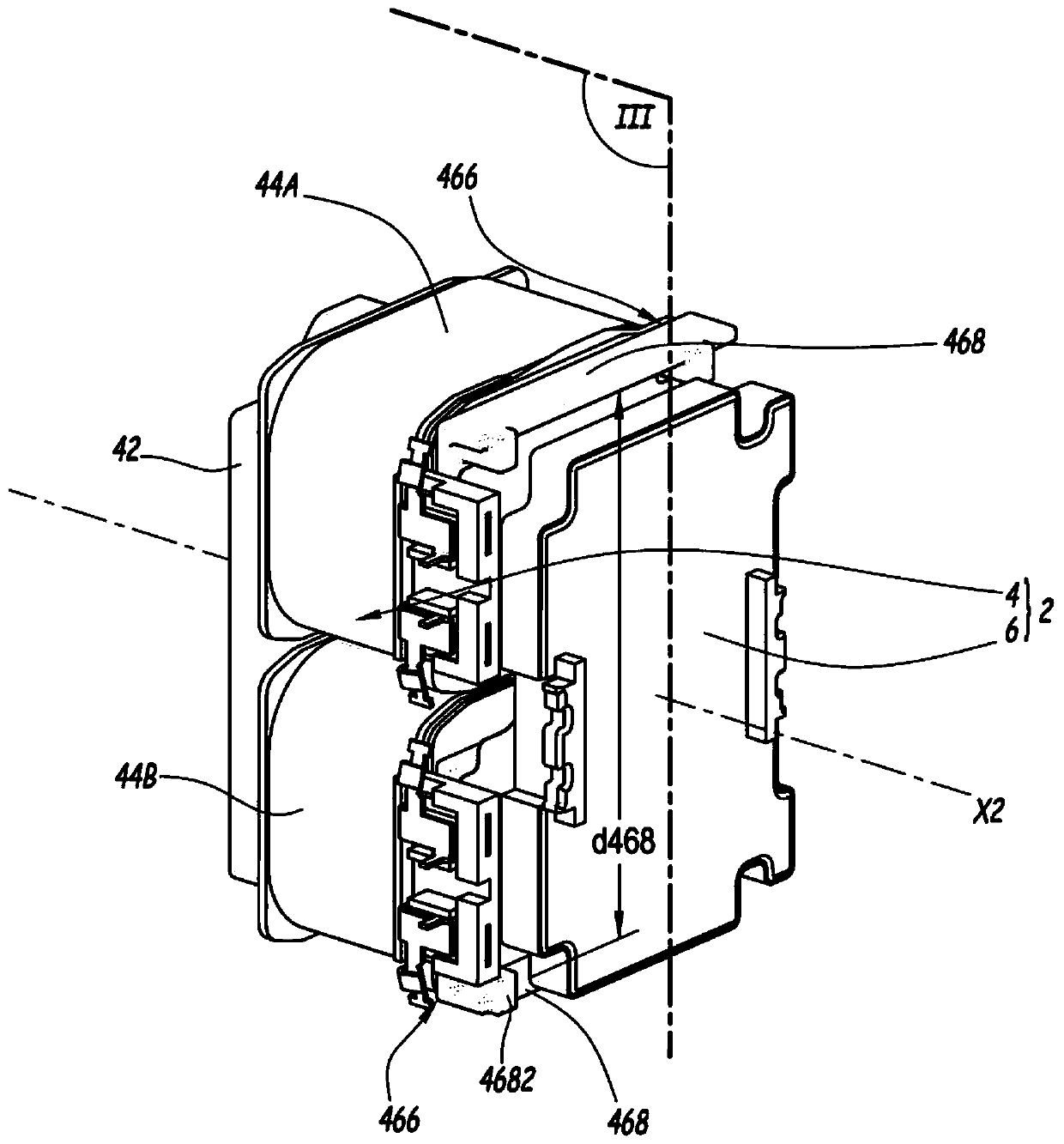
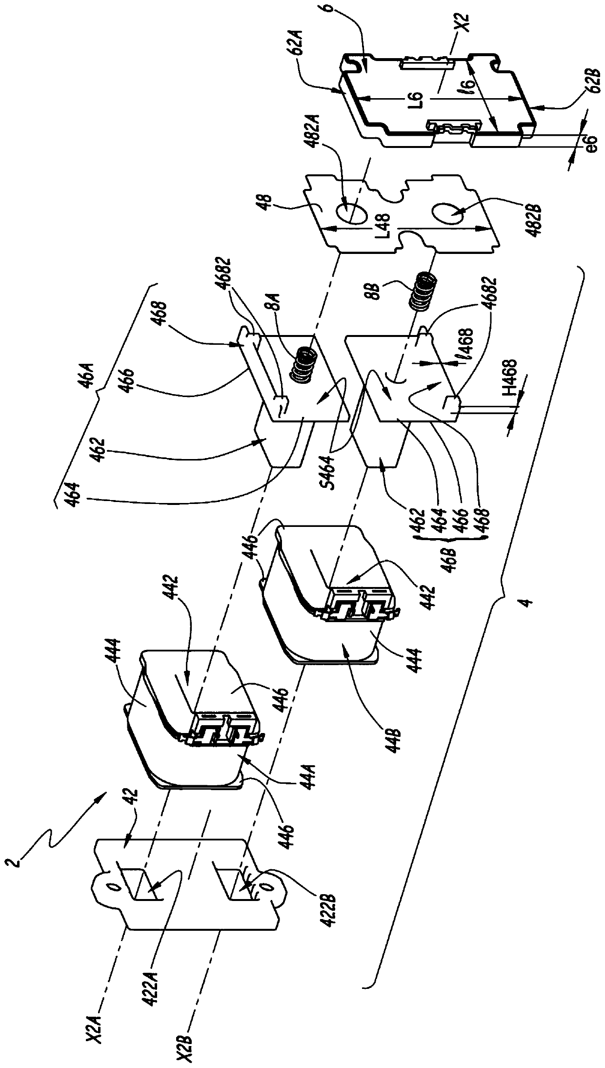
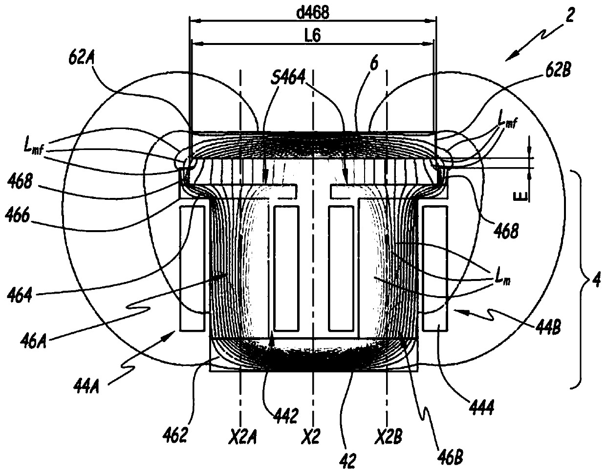
[0026] figure 1 and 2 shows an electromagnetic actuator 2, which is designed for incorporation in Figure 5 In the electrical contactor 200 shown. The actuator 2 comprises a fixed part 4 and an armature 6 movable in translation with respect to the fixed part 4 on the longitudinal axis X2 of the actuator 2 .

[0027] The fixed portion 4 includes a base plate 42 , two identical coils 44A and 44B, two identical cores 46A and 46B, and an air gap spacer 48 . Base plate 42 incorporates two identical orifices 422A and 422B, each centered on axis X2A or X2B, parallel to longitudinal axis X2. Because the coil and core are identical, only coil 44A and core 46A are described in detail. The coil 44A defines a socket 442 around which a winding 444 is wound, disposed between two end plates 446 . The socket 442 for the coil 44A is centered on the axis X2A, while the socket 442 for the coil 44B is centered on the axis X2B. Core 46A incorporates a leg 462 designed to pass through socket ...


PUM


Abstract

An electromagnetic actuator (2) for manipulating electrical contacts comprises a stationary part (4) comprising: at least one coil (44A, 44B), centered on the longitudinal axis (X2), for generating a magnetic field; at least one core a portion (46A, 46B) for concentrating magnetic flux, the core being fitted within the coil and having a fan-out plate (464) for the magnetic flux defining an active surface perpendicular to the longitudinal axis (S464); and at least one magnetic flux return element (42). The actuator also includes an armature (6) and at least one member (8A, 8B), the armature is positioned relative to the fixed part (4) between a first position and a second position under a load induced by a magnetic field Translational movement along the longitudinal axis (X2), a first position away from the active surface (S464), a second position close to the surface, at least one member for elastically returning the armature (6) to the first position and the second position Book a spot. The fan-out plate (464) has at least one rib (468) for closing the magnetic field lines between the fan-out plate and the armature (6), wherein the rib protrudes on the armature side relative to the active surface (S464) and Arranged at the height of the edge (466) of the fan-out plate.

Description

technical field [0001] The invention relates to an electromagnetic actuator for operating an electrical contactor and an electrical contactor comprising such an actuator. Background technique [0002] In the field of electromagnetic actuators it is known, for example from FR-A-2979745, to use coils to generate a magnetic field to control a spring-loaded movable armature. The electromagnetic power required to operate the armature is high, not least due to the large air gap between the armature and the diffuser plate, which is constructed as an extension to the core inserted into each coil. One way to reduce this power involves increasing the active matching surface area of ​​the diffuser plate and armature. This is associated with an increase in the moving mass (ie the mass of the armature) and over-dimensioning of the return spring to ensure compliance with shock resistance requirements. The overdimensioning of this spring results in an increase in the required electromagn...

Claims


Application Information

Patent Timeline
Patent Type & Authority Patents(China)
IPC IPC(8): H01H50/40
CPCH01H1/20H01F7/1638H01H50/14H01H50/163H01H50/40H01H51/06H01F2007/1692H01F7/1646H01H3/28H01H51/2209
Inventor P.拉尔谢V.格弗罗伊
Owner SCHNEIDER ELECTRIC IND SAS
Why Eureka
Try Eureka