Single-phase electronically commutated motor

An electronic commutation, single-phase technology, applied in the direction of electrical components, electromechanical devices, electric components, etc., can solve the problems of lower motor efficiency, inequality, large average air gap, etc., and achieve the effect of avoiding lamination offset

Active Publication Date: 2020-06-12
PIERBURG PUMP TECH
View PDF6 Cites 0 Cited by
  • Summary
  • Abstract
  • Description
  • Claims
  • Application Information

AI Technical Summary

Problems solved by technology

However, the asymmetrical shape of the pole piece edge facing the rotor results in unequal air gaps and thus a larger average air gap between the motor stator and the motor rotor
A large average air gap directly reduces the efficiency of the motor

Method used


Image

  • Single-phase electronically commutated motor
  • Single-phase electronically commutated motor
  • Single-phase electronically commutated motor

Examples


Embodiment Construction

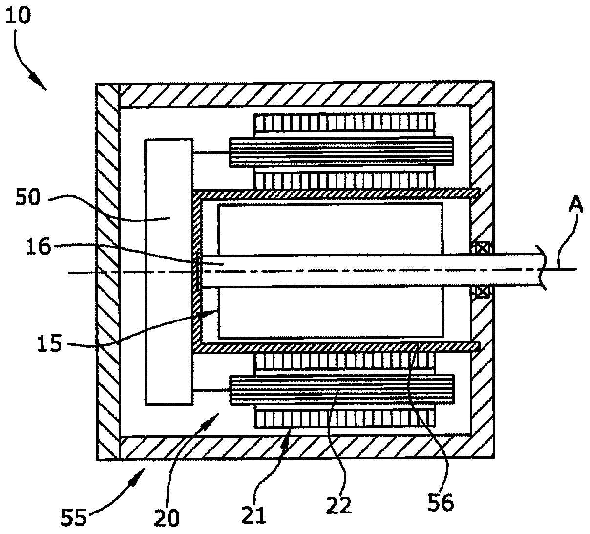
[0020] figure 1 A single phase electronically commutated electric machine 10 is shown provided with a permanent magnet electric machine rotor 15 rotatably attached to a motor shaft 16 . The motor 10 is also provided with a motor stator 20 including a laminated stator body 21 and stator coils 22 . The electric machine 10 includes a motor control unit 50 electrically connected to the stator coils 22 to energize the stator coils 22 . The motor 10 also includes a motor housing 55 and a motor can 56 .

[0021] The electric machine 10 is provided as a so-called canned electric machine, in which the electric machine can 56 fluidly separates the electric machine rotor 15 from the electric machine stator 20 . The motor rotor 15 is arranged inside the motor can 56 , and the surrounding motor stator 20 is arranged outside the motor can 56 . The motor rotor 15 is rotatable about the axis of rotation A and is non-rotatably attached to the motor shaft 16 .

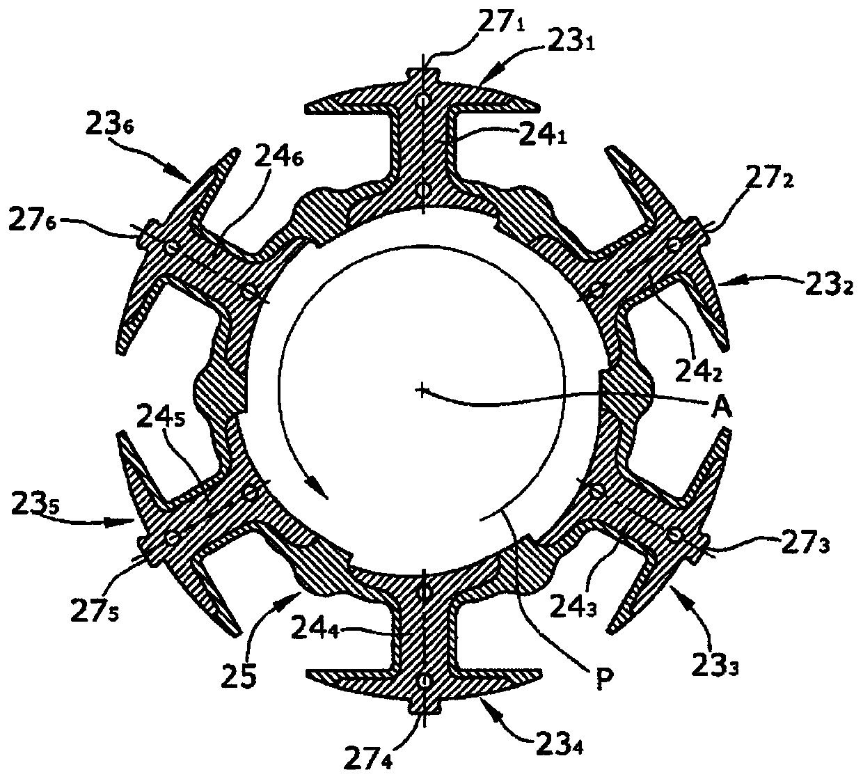
[0022] figure 2 A radial s...


PUM


Abstract

A single-phase electronically commutated motor (10) with a motor rotor (15) and with a laminated stator body (21) comprising at least one set (231-236) of ferromagnetic lamination sheets (28) positively connected to each other by axial punch protrusions (37, 38) wherein the lamination sheet set (231-236) defines a plurality of pole teeth (241-246) with pole shoes (30), the pole teeth (241-246) being provided with a plurality of stator coils (22), wherein the rotor-facing pole shoe edge (33) is shaped asymmetrically with respect to a radial pole tooth centerline (M), so that the rotor-facing pole shoe edge (33) defines a non-constant air gap (36) between the stator pole shoe (30) and the motor rotor (15), wherein each stator pole tooth (241-246) comprises an axial punch protrusion (38) radially arranged close to the rotor-facing pole shoe edge (33) so that the distance between the punch protrusion edge and the rotor-facing pole shoe edge (D1) is less than the distance between the punchprotrusion edge and any other lamination sheet edge (D2).

Description

technical field [0001] The invention relates to a single phase electronically commutated electric machine having a rotor and a laminated stator body. Background technique [0002] These electric machines are provided with a stator body comprising at least one set of ferromagnetic laminations. Laminated stator bodies avoid or at least suppress eddy currents that reduce the efficiency of the motor. The laminations of the laminated stator body are stacked in the axial direction of the motor and are reliably connected to each other by axial stamping protrusions, which means that a set of laminations is provided with the same and engaging stamping protrusions to ensure the precise diameter of the laminations to each other to align. The result of the stamping process is a mechanical deformation of the lamination, in particular of the metal microstructure, such that the magnetic permeability of the lamination changes in the area of ​​the stamping protrusion. [0003] A single-ph...

Claims


Application Information

Patent Timeline
Patent Type & Authority Applications(China)
IPC IPC(8): H02K29/03
CPCH02K29/03H02K2201/03H02K2201/09H02K2213/03
Inventor T.亨克R.帕茨纳
Owner PIERBURG PUMP TECH
Why Eureka
Try Eureka