Double-head vertebral dilator

A dilator and vertebral body technology, applied in the field of double-headed vertebral body dilators, can solve the problem of long operation process, and achieve the effects of reducing the number of radiations, reducing the operation cost and shortening the time.

Active Publication Date: 2017-05-31
常州凯耀医疗器械有限公司
View PDF10 Cites 0 Cited by
  • Summary
  • Abstract
  • Description
  • Claims
  • Application Information

AI Technical Summary

Problems solved by technology

[0004] In order to solve the defect in the prior art that the operation process is relatively long when using traditional vertebral body dilators, the present invention provides a double-headed vertebral body dilator

Method used


Image

  • Double-head vertebral dilator
  • Double-head vertebral dilator
  • Double-head vertebral dilator

Examples


Embodiment 1

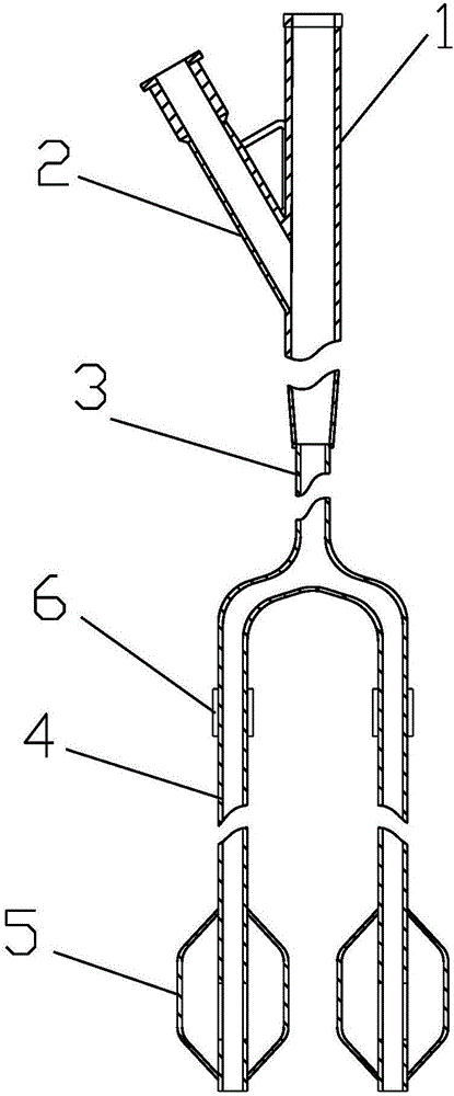
[0018] Such as figure 1 As shown, a double-headed vertebral body expander includes a three-way joint, a catheter 3, a support wire (not shown) and a balloon 5; the three-way joint is Y-shaped, and the three-way joint It includes a direct head 1 and a side joint 2 on one side of the direct head 1, one end of the direct head 1 and one end of the side joint 2 are provided with a one-way valve, and the conduit 3 is fixedly arranged on the direct One end of the head 1, the bottom of the conduit 3 is provided with two branch pipes 4, and the junctions of the two branch pipes 4 and the conduit 3 meet at one end of the conduit 3, the branch pipe 4 and the conduit 3 The connection is smooth and transitional, the ends of the two branch pipes 4 are provided with the balloon 5, and the balloon 5 communicates with the inner cavity of the branch pipe 4, and the two branch pipes 4 are provided with limit marking rings 6, so The support wire passes through the direct head 1 and the conduit 3...

Embodiment 2

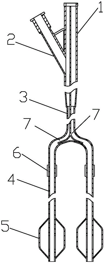
[0021] Such as figure 2 As shown, the difference from Example 1 is that two passages 7 respectively extending to the two branch pipes 4 are provided in the direct head 1, and the direct head 1, the conduit 3, the branch pipe 4 and the passage 7 Each has a gap, and the side joint 2 communicates with the branch pipe 4 through the gap. Other structures are with embodiment 1. The setting of the channel 7 is convenient for inserting the support wire into the branch pipe 4, so as to prevent two support wires from entering the same branch pipe 4, which is convenient to operate and prevents misoperation.

Embodiment 3

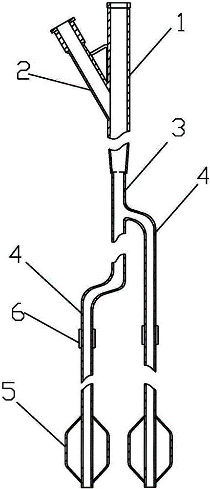
[0023] Such as image 3 As shown, the difference from Embodiment 1 lies in that the positions of the joints between the two branch pipes 4 and the conduit 3 are different. Other structures are with embodiment 1. This kind of setting does not require the channel 7 structure in Embodiment 2. When inserting the support wire, it only needs to be bent at the junction of the catheter 3 and the corresponding branch pipe 4, and the insertion can be performed smoothly. The structure is simple, the operation is convenient, and the cost is low.


PUM


Abstract

The invention belongs to the technical field of medical apparatus and instruments, and relates to a double-head vertebral dilator. The double-head vertebral dilator comprises a three-way connector, a catheter, support wires and saccules, the catheter is installed at one end of the three-way connector, two branch pipes are arranged at the bottom of the catheter, the saccules are arranged at the ends of the branch pipes, the saccules are communicated with inner cavities of the branch pipes, limiting mark rings are arranged on the branch pipes, and the support wires are movably arranged inside the branch pipes. The double-head vertebral dilator has the advantages that the two branch pipes are arranged and can be inserted into the two sides of a vertebral body simultaneously, the sizes and the positions of the two saccules can be observed simultaneously through an X-ray film, X-ray radiation does not need to be conducted separately, the radiation frequency can be reduced, the surgical process and the time are shortened, manpower is saved, and the surgical cost is lowered.

Description

technical field [0001] The invention belongs to the technical field of medical instruments, in particular to a double-headed vertebral body expander. Background technique [0002] The aging population in my country is becoming more and more serious, and the number of patients with osteoporosis and vertebral compression fractures caused by it is increasing year by year. Surgical treatment of vertebral compression fractures is increasing. The vertebral body dilator is suitable for use in combination with vertebroplasty instruments, and is mainly used to expand the vertebral body to form a cavity during the balloon-expanded kyphoplasty operation, so as to inject bone cement to restore and stabilize the vertebral body. [0003] During the operation, two cavities are generally formed in the vertebral body to fill the interior of the vertebral body with bone cement, that is, insert the expander on one side of the vertebral body to form a cavity, and then insert the expander on the...

Claims


Application Information

Patent Timeline
Patent Type & Authority Applications(China)
IPC IPC(8): A61M25/10A61M29/04A61B17/88
CPCA61M25/0021A61M25/0043A61M25/09A61M25/1011A61M25/10181A61M29/02A61B17/8816A61M2210/1003A61M2025/09008
Inventor 童凯徐凯
Owner 常州凯耀医疗器械有限公司
Why Eureka
Try Eureka