Method for acquiring standard axial view of vertebral pedicle

A pedicle and standard axis technology, applied in the medical field, can solve the problems of inability to accurately display the perspective angle, long perspective time, and difficult alignment.

Active Publication Date: 2016-11-23
苏州铸正机器人有限公司
View PDF28 Cites 3 Cited by
  • Summary
  • Abstract
  • Description
  • Claims
  • Application Information

AI Technical Summary

Problems solved by technology

[0004] However, the area of ​​the X-ray image taken by the C-arm X-ray machine is small, the perspective angle cannot be accurately displayed, and the alignment is difficult. Experienced doctors also need to adjust the posture of the C-arm many times. According to each X-ray image Rotate the C-arm until the two rings on the front and rear surfaces of the pedicle axis in the X-ray dia...

Method used


Image

  • Method for acquiring standard axial view of vertebral pedicle
  • Method for acquiring standard axial view of vertebral pedicle
  • Method for acquiring standard axial view of vertebral pedicle

Examples


Embodiment 1

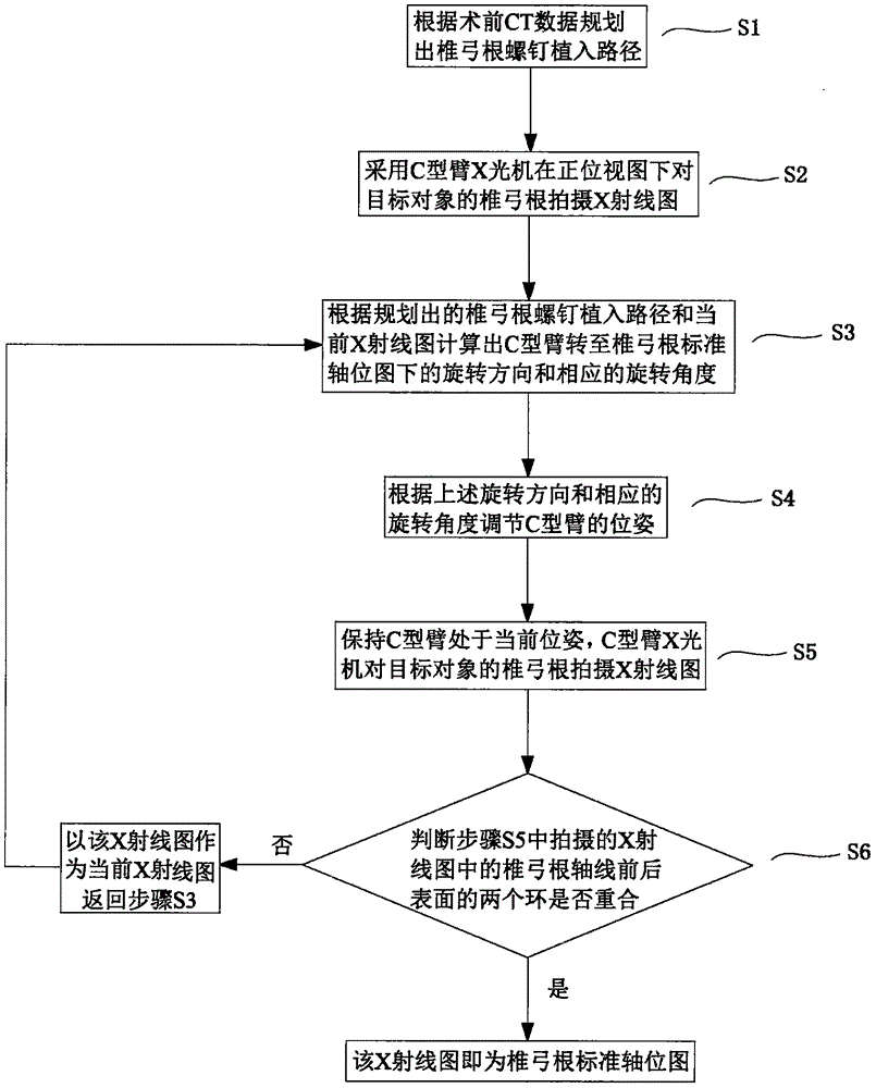
[0031] refer to figure 1 , in the present embodiment, the method for obtaining the standard axial view of the pedicle comprises the following steps:

[0032] S1. Plan the pedicle screw implantation path according to the preoperative CT data;

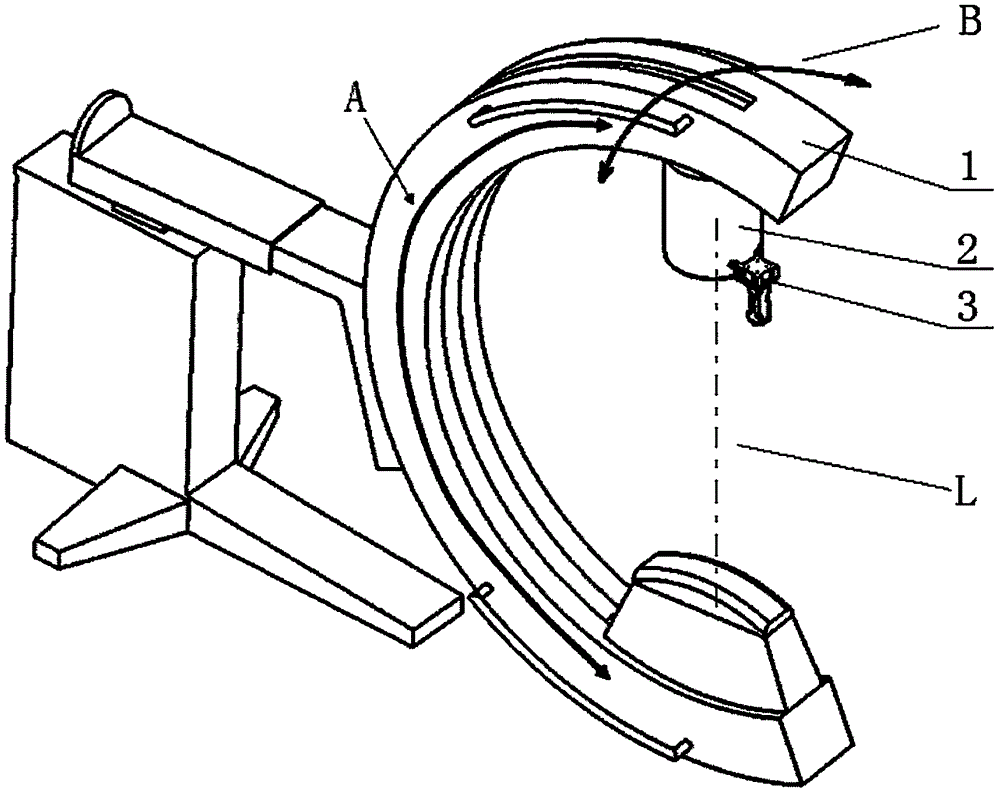
[0033] S2. Use a C-arm X-ray machine to take an X-ray image of the pedicle of the target subject under the frontal view (in clinical practice, the process is mostly that the operator first finds the position of the pedicle by pressing the body of the target subject, Then place the C-arm 1 at a position where the center of the pedicle of the target object is located on the emission axis of the C-arm X-ray machine. At this time, the C-arm X-ray machine is in the front view. It can be understood that this The process is completed by the operator, and the obtained orthometric Figure 1 generally not the standard orthographic view);

[0034] S3. According to the planned pedicle screw implantation path and the current X-ray image, calculate...

Embodiment 2

[0070] The difference from Embodiment 1 is that the angle detector 4 is not installed on the positioning frame 3, but refers to Figure 6 , a bracket 5 is fixed at the middle position of the C-arm 1, and "fixed" here means that the bracket 5 keeps its relative position unchanged when the C-arm 1 rotates, and it can be detachable or non-detachable fixed (cannot be removed or reinstalled after removal). The angle detector is fixed on the bracket 5, where "fixed" means that the bracket 5 can drive the angle detector 4 to rotate with the C-arm 1, The angle detector 4 can detect the angle that the C-arm 1 has turned in real time. Those skilled in the art can choose how to fix the angle detector 4 according to the performance of the angle detector 4 to ensure that the angle detector 4 can measure the C-arm in real time. 1 The angle that has been rotated in a certain direction of rotation.

[0071] Before step S4 is executed (it can be any moment before step S4 is executed, not limi...


PUM


Abstract

The invention relates to the field of medicine, in particular to a method for acquiring a standard axial view of the vertebral pedicle. The method comprises the following steps that S1, a pedicle screw implanting path is planned according to preoperative CT data; S2, an X-ray diagram of the vertebral pedicle of a target object is shot through a C arm X-ray machine in a normal view; S3, the rotating direction and the corresponding rotating angle of a C arm rotating to the standard axial view of the vertebral pedicle are calculated according to the planned pedicle screw implanting path and the current X-ray diagram; S4, the pose of the C arm is adjusted according to the rotating direction and the corresponding rotating angle. Therefore, the needed further rotating direction and the corresponding rotating angle of the C arm rotating to be in the standard axial view of the vertebral pedicle are calculated by combining the pre-planned pedicle screw implanting path and the current C arm pose reflected by the X-ray diagram, then the C arm is rotated according to the rotating direction and the corresponding rotating angle, high goal orientedness is achieved, and the standard axial view of the vertebral pedicle can be fast obtained.

Description

technical field [0001] The invention relates to the field of medicine, in particular to a method for obtaining a standard axial view of the pedicle. Background technique [0002] In the prior art, due to the stenosis of the pedicle, once the screw passes through the side wall of the pedicle, the operation will fail. However, the implantation of the pedicle screw currently depends on the experience of the doctor, and the failure rate of the operation is as high as 30%. [0003] The ideal method of operation is to use the principle of pedicle standard axis positioning, which is to make the axis of the pedicle overlap with the emission axis of the C-arm X-ray machine as much as possible, so that the peripheral geometric shape of the pedicle can be seen in real time And size, as long as the screw does not exceed the peripheral shape, the operation can be very safe. [0004] However, the area of ​​the X-ray image taken by the C-arm X-ray machine is small, the perspective angle c...

Claims


Application Information

Patent Timeline
IPC IPC(8): A61B34/10A61B6/03
Inventor 谢东儒胡磊郭娜王利峰胡宁
Owner 苏州铸正机器人有限公司
Why Eureka
Try Eureka