Pneumatic particle separator

A technology of particle separator and separation chamber, which is applied in the direction of climate sustainability, climate change adaptation, and devices with reverse axial direction of swirl flow, which can solve untimely reaction blockage, high temperature, inability to separate fine particle size, etc. question

Active Publication Date: 2017-05-31
深圳市旋风流体科技有限公司
View PDF10 Cites 0 Cited by
  • Summary
  • Abstract
  • Description
  • Claims
  • Application Information

AI Technical Summary

Problems solved by technology

Chemical catalysis faces the problem of untimely reaction blockage and reaction high temperature, and cyclone dust removal faces the problem of not being able to separate fine particles

Method used


Image

  • Pneumatic particle separator
  • Pneumatic particle separator
  • Pneumatic particle separator

Examples


Embodiment 1

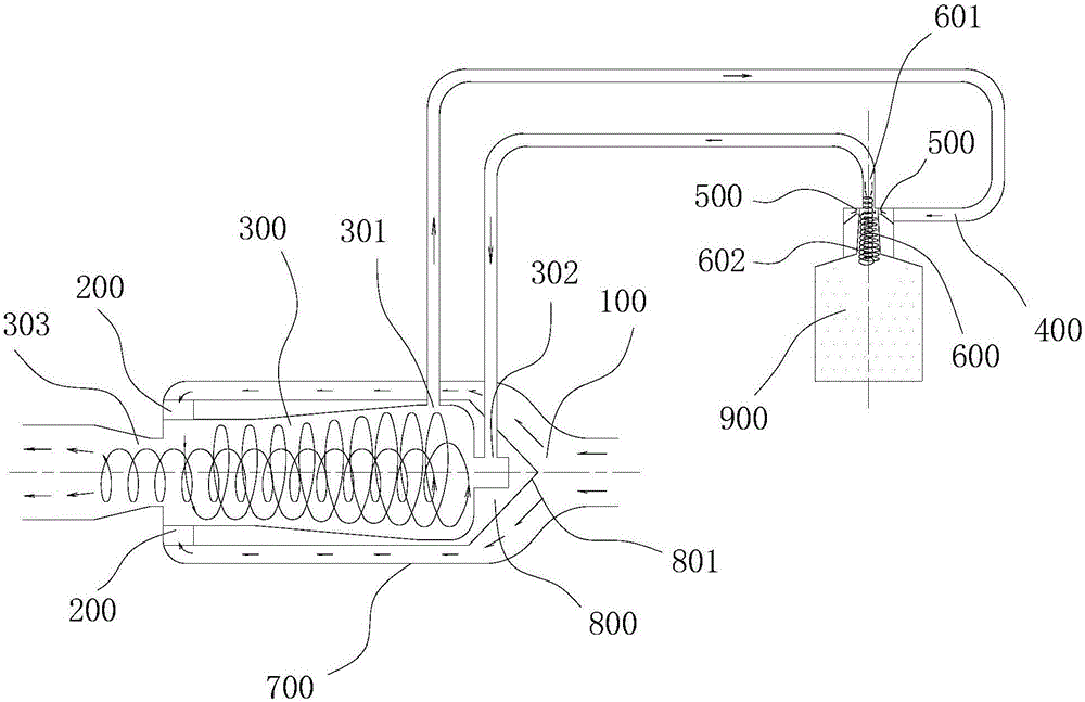
[0032] This embodiment provides a pneumatic particle separator, which can be used to separate the solid phase (such as dust) and the gas phase in the gas-solid mixture.

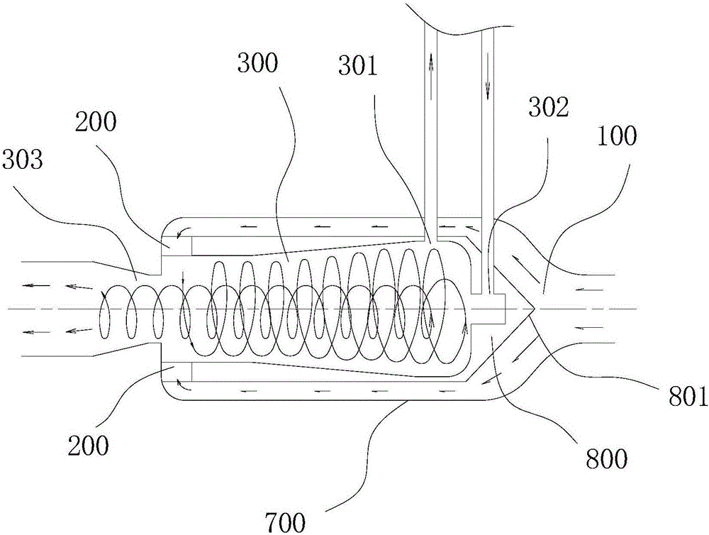
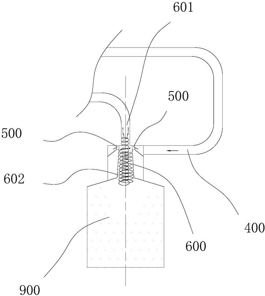
[0033] Please refer to Figure 1-3 , the pneumatic particle separator includes a main separation device and a dust collection device. The main separation device and the dust collection device can be cycled for multiple separation operations.

[0034] Specifically, the main separation device includes a first inlet channel 100 , a first cyclone 200 and a separation chamber 300 . This first cyclone 200 is installed on the first inlet channel 100, and the separation chamber 300 communicates with the first cyclone 200, and the first cyclone 200 can make the gas-solid mixture form a swirling flow (rotation) in the separation chamber 300 airflow). The swirling flow can make the solid phase and the gas phase rotate along different paths, the solid phase will rotate close to the wall of the separation chamber 300 ,...


PUM


Abstract

The invention discloses a pneumatic particle separator. The pneumatic particle separator comprises a main separation device and a dust collecting device. The main separation device includes a first intake channel, a first cyclone and a separation cavity. The dust collecting device includes a second intake channel, a second cyclone and a separation channel. The first cyclone is mounted on the first intake channel; the separation cavity is communicated with the first cyclone; and the first cyclone can enable a gas-solid mixture to form a rotational flow in the separation cavity. The separation cavity is provided with a dust outlet, an air return port and a main exhaust port. The second intake channel is communicated with the dust outlet; the second cyclone is mounted on the second intake channel; and the separation channel is communicated with the second cyclone, and is provided with a discharge port for discharging a solid phase and a secondary exhaust port communicated with the air return port. As the main separation device and the dust collecting device can realize circular conduction, the returned air flow is used for realizing efficient gas-solid separation; and meanwhile, the two-grade coupled separator reduces the exhaust residual dust quantity.

Description

technical field [0001] The present application relates to particle separators, in particular to a pneumatic particle separator. Background technique [0002] The current common principles of particle separators and dust collectors include pneumatic, chemical catalysis and absorption, adsorption and filtration. Pneumatic particle separator is a device that is driven by pressure difference and realizes gas-solid mixture gas phase and solid phase separation through pneumatic principle. It is often used in automobile exhaust treatment, air purification, particle recovery, etc. [0003] At present, the main principles of common pneumatic particle separators include filter type, chemical catalyst and cyclone dust collector. Among them, the filter type particle separator faces the problem of particle clogging. Chemical catalysis faces the problem of untimely reaction blockage and reaction high temperature, and cyclone dust removal faces the problem of inability to separate fine pa...

Claims


Application Information

Patent Timeline
Patent Type & Authority Applications(China)
IPC IPC(8): B04C5/24B04C5/30B04C7/00
CPCB04C5/24B04C5/30B04C7/00Y02A50/2351
Inventor 李航越李天维汪京涛
Owner 深圳市旋风流体科技有限公司
Why Eureka
Try Eureka