Railway self-dumping car chassis

A self-tipping car and underframe technology, applied in railway car body parts, underframes, transportation and packaging, etc., can solve the problems of difficult installation and disassembly, hidden safety hazards for operators, insufficient strength and rigidity, etc., to achieve convenient installation and maintenance, avoid Safety hazard, high strength and stiffness effect

Active Publication Date:
View PDF6 Cites 5 Cited by
  • Summary
  • Abstract
  • Description
  • Claims
  • Application Information

AI Technical Summary

Problems solved by technology

[0003] The underframe of a traditional railway self-rolling car includes an end beam, a corbel and a middle beam. The middle beam is assembled and welded by I-beams. The disadvantages of this structure are: complex structure, heavy weight, high cost, and low strength and rigidity , poor load capacity
[0004] In addition, the traditional railway self-dumping car pushes the carriage to tip over through the tipping transmission device (usually a hydraulic cylinder) installed on the chassis. However, the strength and rigidity of the hydraulic cylinder bracket on the existing chassis are insufficient, and installation and disassembly are difficult. , is not conducive to maintenance
[0005] In addition, the end beam mechanism of traditional railway self-rollover vehicles is not equipped with protective structures, which brings major safety hazards to operators

Method used


Image

  • Railway self-dumping car chassis
  • Railway self-dumping car chassis
  • Railway self-dumping car chassis

Examples


Embodiment Construction

[0032] Below in conjunction with accompanying drawing and specific embodiment the present invention is described in further detail:

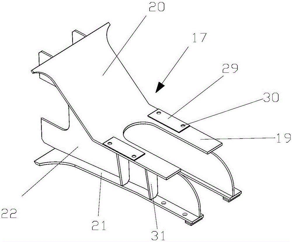
[0033] Shown in the figure is a kind of railway self-rollover underframe of the present invention, which includes a middle beam 1, two symmetrically arranged end beam mechanisms 2 fixed at both ends of the middle beam 1 and vertically fixed thereto, and two symmetrically arranged on the middle beam 1 The corbel mechanism 3, and two symmetrically arranged hydraulic cylinder support mechanisms 4 are also arranged between the two corbel mechanisms 3;

[0034] The middle sill 1 adopts a box structure or a double H-shaped structure, which consists of an upper cover 5, a lower cover 6, and two fish-belly webs 7 arranged in parallel between the upper cover 5 and the lower cover 6. Composition; on the upper cover plate 5 of the center sill 1, several adjusting wear plates 35 are arranged at intervals. The adjustment wear plate 35 can be used in conjunc...


PUM


Abstract

The invention discloses a railway self-dumping car chassis. The railway self-dumping car chassis comprises a middle beam, two end beam mechanisms and two sleeper beam mechanisms, wherein the two end beam mechanisms are arranged at two ends of the middle beam symmetrically and are perpendicularly fixed to the middle beam, and the two sleeper beam mechanisms are arranged on the middle beam symmetrically. Two hydraulic cylinder support mechanisms are arranged between the two sleeper beam mechanisms symmetrically. The middle beam comprise an upper cover plate, a lower cover plate and two parallel fish-belly-type web plates arranged between the upper cover plate and the lower cover plate. Each end beam mechanism comprises an end beam, ladders, an anti-slip protection plate and handrail devices, wherein the end beam is arranged on the upper cover plate and perpendicularly fixed to the upper cover plate, the ladders are arranged below two ends of the end beam symmetrically and are perpendicularly fixed to the bottom end face of the end beam, the anti-slip protection plate is arranged on one side, close to the corresponding sleeper beam mechanism, of the end beam, and the handrail devices are arranged on one side, far away from the corresponding sleeper beam mechanism, of the end beam. The railway self-dumping car chassis has the advantages that the requirement on mounting a hydraulic cylinder tipping transmission device on the railway self-dumping car chassis is met, and the railway self-dumping car chassis is small in self weight, simple in structure, convenient to mount and maintain and capable of meeting the application requirements of a railway self-dumping car in severe environments.

Description

technical field [0001] The invention relates to the technical field of railway self-rollover vehicles, in particular to an underframe of railway self-rollover vehicles. Background technique [0002] The railway self-dumping car is a special vehicle that combines unloading equipment and vehicle structure, and is suitable for transporting bulk goods such as ore, gravel, coal, and building materials. The railway self-dumping car has a car that can be tipped and unloaded. [0003] The underframe of a traditional railway self-rolling car includes an end beam, a corbel and a middle beam. The middle beam is assembled and welded by I-beams. The disadvantages of this structure are: complex structure, heavy weight, high cost, and low strength and rigidity , Poor load capacity. [0004] In addition, the traditional railway self-dumping car pushes the carriage to tip over through the tipping transmission device (usually a hydraulic cylinder) installed on the chassis. However, the stre...

Claims


Application Information

Patent Timeline
Patent Type & Authority Applications(China)
IPC IPC(8): B61F1/02B61F1/10B61F1/14B61F1/08
CPCB61F1/02B61F1/08B61F1/10B61F1/14
Inventor 石峰汤楚强吴宇波金晓平郑传平
Why Eureka
Try Eureka