Safety braking device for gear and rack type lifting device

A technology for lifting equipment and safe braking, which is used in elevators, transportation and packaging, elevators in buildings, etc., and can solve problems such as driving gear problems, hidden dangers, wear of friction materials, etc.

Active Publication Date: 2017-05-31
TAICANG DENASEN MECHANICAL & ELECTRICAL ENG CO LTD
View PDF5 Cites 3 Cited by
  • Summary
  • Abstract
  • Description
  • Claims
  • Application Information

AI Technical Summary

Problems solved by technology

[0002] The safety braking measures of the existing rack and pinion lifting equipment are realized either by braking the motor shaft or by braking the gear shaft. These methods belong to the friction braking method, and there may be friction Safety hazards caused by material wear or oil pollution; in addition, if there is a problem with the drive gear, the above method will be powerless; and it is possible to have a problem with the drive gear. Therefore, in order to ensure safety, the rack and pinion lifting equipment must be Equipped with a reliable safety brake device that can deal with problems including drive gears and similar safety problems

Method used


Image

  • Safety braking device for gear and rack type lifting device
  • Safety braking device for gear and rack type lifting device
  • Safety braking device for gear and rack type lifting device

Examples


Embodiment 1

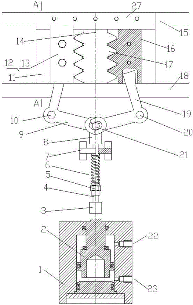
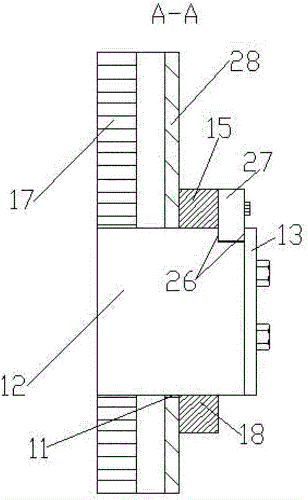
[0028] Example 1, Figure 12 It is a schematic diagram of Embodiment 1, the drawing shows the appearance of the side of the lifting equipment, the safety brake device is installed on the rack and pinion lifting equipment and is temporarily in a free position, the lifting equipment is ready to run or is running, Figure 13 It is a schematic diagram of the situation where the safety braking device of embodiment 1 brakes the lifting equipment, (the left and right described in the previous figure are viewed from the inside of the lifting equipment to the side of the lifting equipment, Figure 12 , 13 It is viewed from the outside to the side of the lifting equipment, so the left and right directions are just opposite), the safety braking device must be installed under the load-bearing structure of the lifting equipment, directly contacting or contacting the load-bearing through the intermediate transition parts, the safety braking device used For a description of the components a...

Embodiment 2

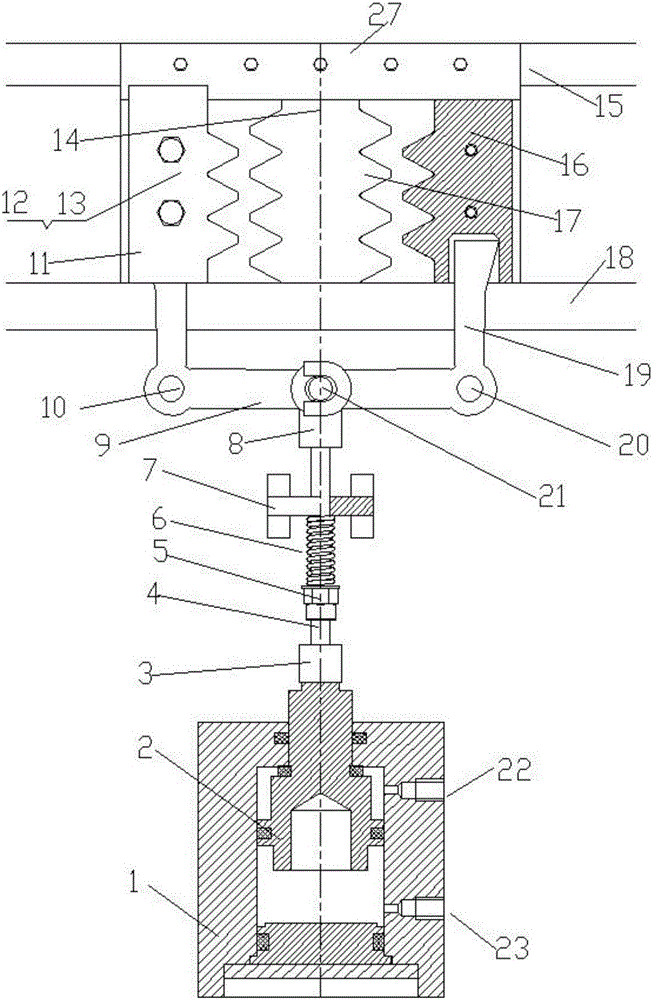
[0029] Example 2, Figure 13 It is also a schematic diagram of embodiment 2, which shows the situation when the solenoid valve is in the reset position and the safety braking device performs braking. Figure 12 It is also a schematic diagram when the solenoid valve is in the working position and the safety brake device is in the free position state in embodiment 2, and the safety brake device adopted is Figure 8 And [0008] paragraph described directly on the safety braking device that is provided with on the hoisting equipment car, the description of each part composition and effect of its internal structure sees Figure 8 As shown in paragraph [0008], because it involves the coordination of multiple transmission systems, special attention should be paid to the quality of manufacture and installation during manufacture and installation, including the things described in paragraph [0011] that must be done well, including accurate Control the work related to the height differenc...

Embodiment 3

[0030] Embodiment 3 is to install the rack-and-pinion elevator using the described independent safety brake assembly, Figure 14 It is a schematic diagram of embodiment 3, which shows the situation when the solenoid valve is in the reset position and the safety braking device performs braking. Figure 15 It is a schematic diagram of when the solenoid valve is in the working position and the safety brake device is in the free position state in embodiment 3. The specific structure of the safety brake device used is an independent safety brake device assembly. The independent safety brake device The load-bearing frame of the component is connected to the load-bearing structure of the elevator car through bolt connection or other connection methods, and the solenoid valve control circuit and input pipeline interface are connected to the electrical control circuit interface and pipeline interface of the elevator. See Figure 10 As shown, and described in paragraph [0009]; its inter...


PUM


Abstract

The invention discloses a safety braking device for a gear and rack type lifting device. A movable rack can move horizontally on a rail assembly or keep at certain determined positions. The top of the movable rack makes direct contact with a main bearing structure of a lifting device lift car after entering a braking state for bearing or makes contact with the main bearing structure through a middle transition bearing part for bearing. An operation mechanism for the movable rack operates the movable rack to horizontally move on a rail hole or stay and keep at certain determined positions, wherein the determined positions include a braking position engaged with a drive rack of the lifting device or a free position completely disengaged from the drive rack of the lifting device and having a certain gap with the drive rack. A rack engagement manner is adopted for conducting safety protection braking, and the beneficial effect of obviously improving the safety protection braking quality is achieved.

Description

technical field [0001] The invention relates to the field of safety braking devices for lifting equipment, in particular to a safety braking device for rack-and-pinion lifting equipment. Background technique [0002] The safety braking measures of the existing rack and pinion lifting equipment are realized either by braking the motor shaft or by braking the gear shaft. These methods belong to the friction braking method, and there may be friction Safety hazards caused by material wear or oil pollution; in addition, if there is a problem with the drive gear, the above method will be powerless; and it is possible to have a problem with the drive gear. Therefore, in order to ensure safety, the rack and pinion lifting equipment must be Equipped with a reliable safety brake that can deal with problems including drive gear and similar safety problems. Contents of the invention [0003] The object of the present invention is to provide a reliable safety braking device capable of...

Claims


Application Information

Patent Timeline
Patent Type & Authority Applications(China)
IPC IPC(8): B66B11/04B66B9/02B66B1/40B66B5/00
CPCB66B1/40B66B5/00B66B9/022B66B11/0461
Inventor 廖忠民
Owner TAICANG DENASEN MECHANICAL & ELECTRICAL ENG CO LTD
Why Eureka
Try Eureka