Automatic poling device for telegraph pole

A technology for pole devices and utility poles, which is applied in the field of automatic pole erection devices for utility poles, which can solve problems such as difficult installation, poor effect, time-consuming and labor-intensive problems, and achieve the effects of reducing labor intensity, saving manpower, and having good effects

Inactive Publication Date: 2017-05-31
JINAN CITY CHANGQING DISTRICT POWER SUPPLY CO OF STATE GRID SHANDONG ELECTRIC POWER CO +1
View PDF8 Cites 1 Cited by
  • Summary
  • Abstract
  • Description
  • Claims
  • Application Information

AI Technical Summary

Problems solved by technology

[0002] At present, electric poles can be seen everywhere, which brings great convenience to the transmission of electric energy and laying of electric wires. However, due to the high requirements on the angle and the general weight of electric poles during installation, it is relatively difficult to install. In the process, the staff usually dig pits of different depths according to the type of utility poles, and most of them use manual methods to erect the poles. The effect is not good and it is time-consuming and laborious, and the labor force is too large, which is very inconvenient

Method used


Image

  • Automatic poling device for telegraph pole
  • Automatic poling device for telegraph pole
  • Automatic poling device for telegraph pole

Examples


Embodiment Construction

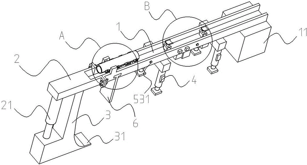
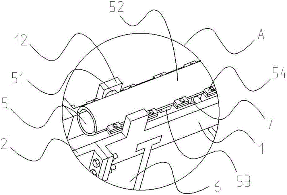
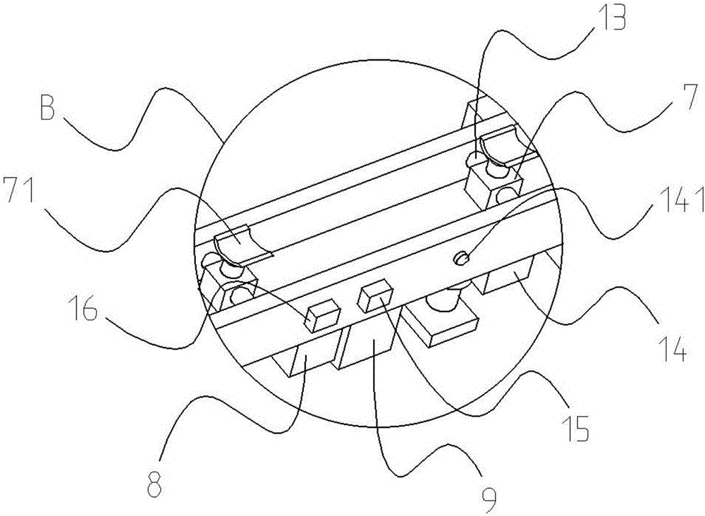
[0027] In order to better understand the present invention, the implementation manner of the present invention will be explained in detail below in conjunction with the accompanying drawings.

[0028] Such as Figure 1 to Figure 6 As shown, an automatic pole erecting device for a utility pole includes an installation body 1, a counterweight 11, a fixed plate 12, a rotating shaft 13, a spirit level 14, a level indicator light 141, a balance switch 15, a pole switch 16, and an installation Body 2, telescoping rod 21, supporting body 3, horizontal plane 31, hydraulic support leg 4, positioning rod cover 5, rod cover rotating column 51, connecting rod cover 52, spirit level two 53, level indicator light two 531, connection block 54, electric wire Rod 55, T-shaped vertical plate 6, hydraulic cylinder 7, curved push plate 71, controller 8, mobile power supply 9, the installation body 1 is provided with a groove, and one end of the installation body 1 is provided with a counterweight...


PUM


Abstract

The invention provides an automatic poling device for a telegraph pole and belongs to the technical field of outdoor working tools. The automatic poling device comprises a mounting body, a balancing switch, a poling switch, a loading body, a positioning pole sleeve and a connecting pole sleeve. A balance weight is arranged at one end of the mounting body, the positions, on the two side of a groove, of the other end of the mounting body are each provided with a fixing plate, and the two sides of the bottom of the mounting body are each provided with two hydraulic supporting legs. A first level gauge and a T-shaped perpendicular plate are arranged at the bottom of the mounting body, the T-shaped perpendicular plate is tangent to the outer surface of the longitudinally-perpendicular positioning pole sleeve, and the diameter of a cylindrical hole between the positioning pole sleeve and the connecting pole sleeve is the same with the external diameter of the telegraph pole. The loading body is fixed to the end face of one end of the positioning pole sleeve of the mounting body through connection of threads, and a supporting body is mounted at the bottom of the loading body. The automatic poling device for the telegraph pole is good in effect and high in practicability, the problem that existing mounting of the telegraph pole is high in labor intensity is solved, manpower can be effectively saved, and the labor intensity is lowered; and meanwhile, the telegraph pole can be stably mounted, and functionality is greatly improved.

Description

technical field [0001] The invention relates to the technical field of outdoor working tools, in particular to an automatic pole erecting device for utility poles. Background technique [0002] At present, electric poles can be seen everywhere, which brings great convenience to the transmission of electric energy and laying of electric wires. However, due to the high requirements on the angle and the general weight of electric poles during installation, it is relatively difficult to install. In the process, the staff usually dig pits of different depths according to the type of utility poles, and most of them use manual methods to erect poles. The effect is not good and it is time-consuming and laborious, and the labor force is too large, which is very inconvenient. Therefore we urgently need a kind of practicability strong, can effectively save manpower, can guarantee the electric pole automatic pole device that electric pole is installed stably simultaneously. Contents o...

Claims


Application Information

Patent Timeline
Patent Type & Authority Applications(China)
IPC IPC(8): E04H12/34
CPCE04H12/34
Inventor 张俊峰姬忠刚赵炜
Owner JINAN CITY CHANGQING DISTRICT POWER SUPPLY CO OF STATE GRID SHANDONG ELECTRIC POWER CO
Why Eureka
Try Eureka