Flip machine box, non-tool operation type locking device thereof and lock

A locking device, tool-less technology, applied in building locks, construction, building construction, etc., can solve the problems of inconvenient use of locking devices, unreliable locking, etc.

Active Publication Date: 2017-05-31
CHINA AVIATION OPTICAL-ELECTRICAL TECH CO LTD
View PDF2 Cites 6 Cited by
  • Summary
  • Abstract
  • Description
  • Claims
  • Application Information

AI Technical Summary

Problems solved by technology

[0004] The purpose of the present invention is to provide a tool-free operation locking device to solve the problems of inconvenient use and unreliable locking of the current locking device; in addition,

Method used


Image

  • Flip machine box, non-tool operation type locking device thereof and lock
  • Flip machine box, non-tool operation type locking device thereof and lock
  • Flip machine box, non-tool operation type locking device thereof and lock

Examples


Embodiment Construction

[0048] Embodiments of the present invention will be further described below in conjunction with the accompanying drawings.

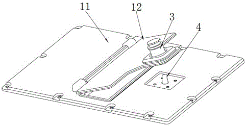
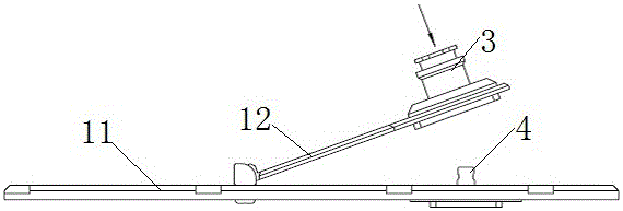
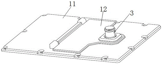
[0049] The specific embodiment of clamshell case of the present invention, as Figure 1 to Figure 7 As shown, the flip case includes a box body and a locking device arranged on the box body, the locking device includes a lock body 3 and a dead bolt 4, wherein the box body includes a box body panel 11 and a flip cover 12 arranged on the box body panel, The deadbolt 4 is arranged on the box body panel 11, and the lock body 3 is provided with a mounting seat, and the lock body 3 is fixed on the flip cover 12 through the mounting seat. In other embodiments, the lock body can also be arranged on the panel of the box body, while the lock tongue 4 is arranged on the flip cover.

[0050] The lock tongue 4 in this embodiment is provided with a lock groove 41 , the diameter of the lock tongue 4 is equivalent to the diameter of the small diameter section 315 of th...


PUM


Abstract

The invention relates to the field of rapid dismounting and locking devices, in particular to a flip machine box, a non-tool operation type locking device thereof and a lock. The non-tool operation type locking device comprises the lock and a locking dog. The lock comprises a fixing sleeve extending in the forward and backward directions. The front end of the fixing sleeve is provided with a mounting structure which forms a mounting base of the lock. The fixing sleeve is provided with a locking hole. The front end of the locking hole is provided with a locking dog inserting opening allowing the locking dog to be inserted. The hole wall of the locking hole is provided with a ball mounting hole penetrating through the side wall of the fixing sleeve. A ball is assembled into the ball mounting hole in a guiding mode. The diameter of the ball is larger than the length of the ball mounting hole. The locking dog is provided with a locking groove used for being in locking fit with the ball. The periphery of the fixing sleeve is sleeved with a mobile sleeve. The fixing sleeve is provided with an elastic locking component used for providing forward acting force for the mobile sleeve. The mobile sleeve is mounted on the fixing sleeve in an abutting mode through the elastic locking component and provided with an abut-pushing wall face and a receding structure. By adoption of the flip machine box, the non-tool operation type locking device thereof and the lock, the problems that existing locking devices are inconvenient to use and unreliable in locking are solved.

Description

technical field [0001] The invention relates to the field of quick-release locking devices, in particular to a clamshell case, a tool-free operating locking device and a lock body thereof. Background technique [0002] At present, the quick release and quick lock locking methods that can be realized without tools mainly include screw locking, sliding locking, etc. Among them, the captive screw is also called the spring screw, which relies on the pressing spring to control the elongation and shortening of the thread, and relies on the thread to control the locking. However, this method is manually tightened, and it is not easy to control whether it is tightened, and it is inconvenient to use. In addition, this locking method lacks anti-loosening measures and is not resistant to vibration. When it is used in a small space, the spring stroke is small, and sometimes it is difficult to judge whether the thread is pressed out during operation, and the locking is unreliable. [00...

Claims


Application Information

Patent Timeline
IPC IPC(8): E05B65/52
CPCE05B65/52
Inventor 郭子昂陈旭辉陈浩宾黄锦源陈广亮程少凡
Owner CHINA AVIATION OPTICAL-ELECTRICAL TECH CO LTD
Why Eureka
Try Eureka