Electronic expansion valve

A technology of electronic expansion valve and valve body, which is applied in the direction of lifting valve, valve details, valve device, etc. It can solve the problems of low precision of the stop position and difficulty in ensuring the movement of the lead screw in place, so as to ensure the movement accuracy, ensure the movement in place, The effect of improving the accuracy of the upper and lower stopper positions

Active Publication Date: 2017-05-31
ZHEJIANG DUNAN ARTIFICIAL ENVIRONMENT
View PDF9 Cites 31 Cited by
  • Summary
  • Abstract
  • Description
  • Claims
  • Application Information

AI Technical Summary

Problems solved by technology

[0006] The purpose of the present invention is to provide an electronic expansion valve to solve the problem that the stop position of the stop

Method used


Image

  • Electronic expansion valve
  • Electronic expansion valve
  • Electronic expansion valve

Examples


Embodiment Construction

[0027] Embodiments of the invention are described in detail below, but the invention can be practiced in many different ways as defined and covered by the claims.

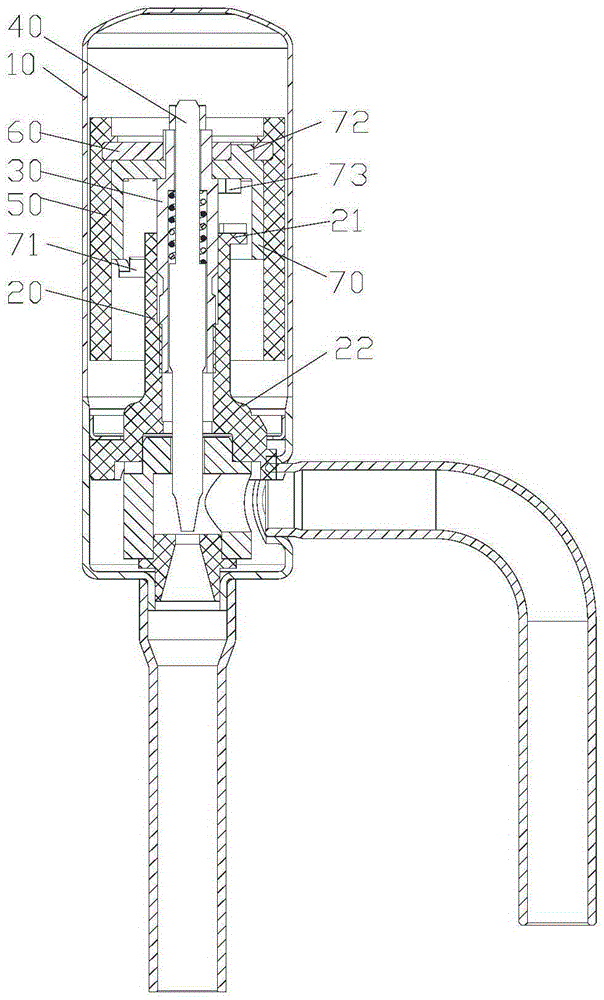
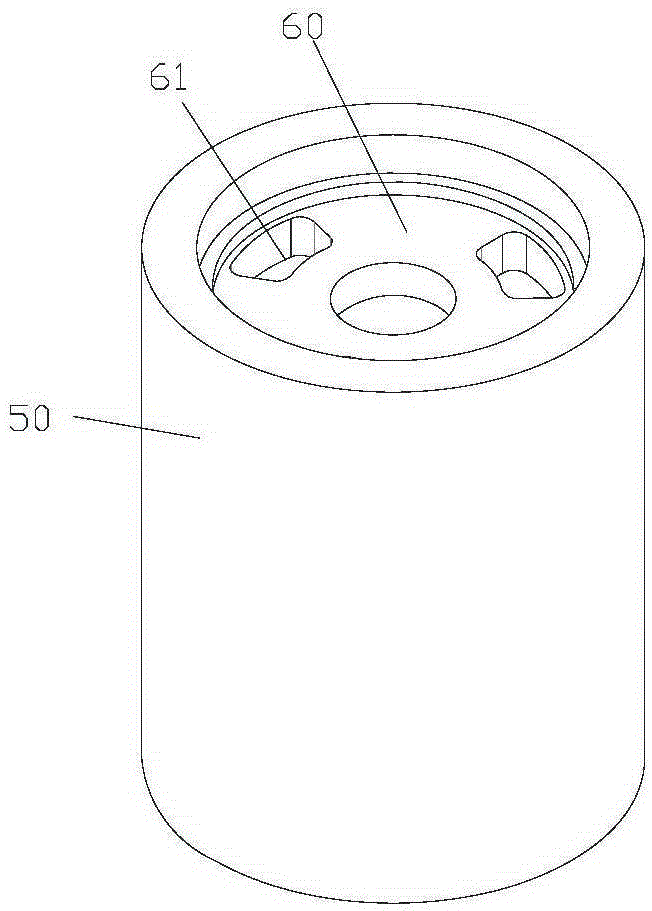
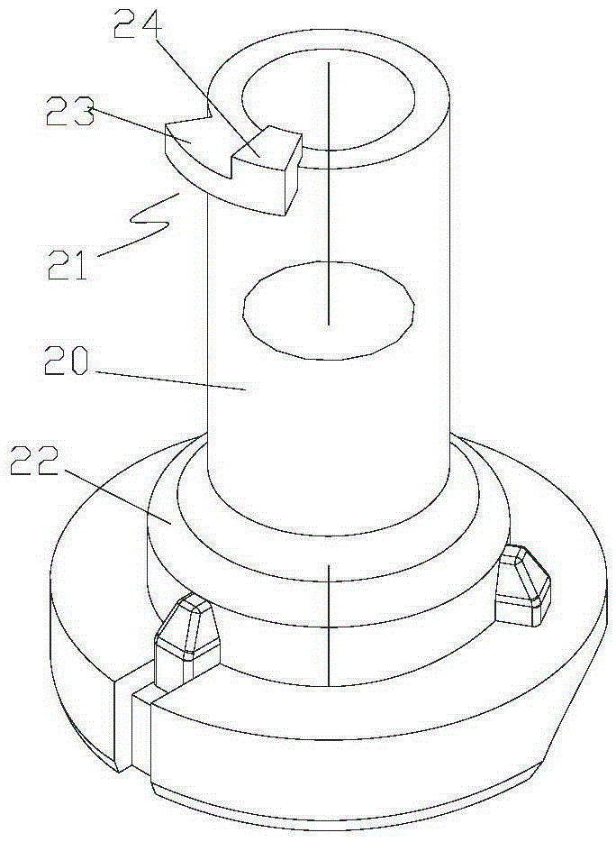
[0028] Please refer to Figures 1 to 8 According to an embodiment of the present invention, the electronic expansion valve includes a valve body 10, a nut 20 assembled on the valve body 10, a screw rod 30 movably assembled in the nut 20, a valve needle 40 installed inside the screw rod 30, And the magnetic rotor 50 that is located on the periphery and covers a part of the nut 20. The screw mandrel 30 is fixed to the connecting plate 60. The magnetic rotor 50 is fixedly connected to the upper end of the screw mandrel 30 through the connecting plate 60. The magnetic rotor 50 drives the screw mandrel 30 to go up and down. The reciprocating motion controls the valve needle 40 to adjust the opening of the valve port located at the bottom of the valve body 10. The electronic expansion valve also includes: a movable stop ...


PUM


Abstract

The invention provides an electronic expansion valve. The electronic expansion valve comprises a valve body, a nut assembled on the valve body, a screw rod movably assembled in the nut, a valve needle arranged inside the screw rod and a magnetic rotor arranged on the periphery and covering a part of the nut, and further comprises a movable check ring and a fixed stop block; the screw rod is fixed to a connecting plate; the magnetic rotor is fixedly connected to the upper end of the screw rod through the connecting plate and drives the screw rod to move vertically in a reciprocating mode; the control valve needle adjusts the opening degree of a valve port located at the bottom of the valve body; the movable check ring is arranged in the magnetic rotor in a sleeved mode and is fixedly connected to the connecting plate; a first stop lug is arranged at the first end, close to the nut, of the movable check ring; and the fixed stop block is integrally formed at the upper end part of the outer periphery of the nut and is matched with the movable check ring to form a circumferential limit. The electronic expansion valve can solve the problems that in the prior art, the stop position precision of stop structures of electronic expansion valves is low and screw rods are difficult to move in place.

Description

technical field [0001] The invention relates to an electronic expansion valve. Background technique [0002] The electronic expansion valve is an important part in the refrigeration system, which mainly plays the role of throttling and reducing pressure and regulating flow. The existing electronic expansion valve includes a valve body, a nut, and a valve needle assembly threadedly engaged with the nut. A driving device is used to drive the valve needle assembly to rotate while generating up and down motion to adjust the opening of the valve port to realize flow control. [0003] In this type of electronic expansion valve, it is usually necessary to provide a stop device to limit the maximum range of the valve needle's up and down movement, to limit the maximum opening and minimum opening of the valve port, or to prevent excessive or unstable movement of the valve needle. The valve itself causes damage. [0004] CN101629649B discloses an electric valve, such as figure 1 As...

Claims


Application Information

Patent Timeline
IPC IPC(8): F16K31/06F16K31/50F16K1/32
CPCF16K1/32F16K31/0655F16K31/504
Inventor 苏鹏王定军刘春王鑫楠
Owner ZHEJIANG DUNAN ARTIFICIAL ENVIRONMENT
Why Eureka
Try Eureka