Bridge monitoring equipment

A technology for monitoring equipment and bridges, applied in mechanical equipment, supporting machines, machines/brackets, etc., can solve the problems of cumbersome disassembly and assembly process, time-consuming and labor-intensive efficiency, affecting normal work, etc., to reduce operation steps and improve installation. Speed, effect of preventing accidental electric shock

Active Publication Date: 2017-05-31
湖南长信建设集团有限公司
View PDF6 Cites 8 Cited by
  • Summary
  • Abstract
  • Description
  • Claims
  • Application Information

AI Technical Summary

Problems solved by technology

When the existing monitoring camera is installed, the camera is usually directly fixed on the pole by screws and then powered by an external line. When the camera fails and needs to be repaired, it must be disassembled by a screwdriver. It is cumbersome, time-consuming, labor-in

Method used


Image

  • Bridge monitoring equipment
  • Bridge monitoring equipment
  • Bridge monitoring equipment

Examples


Embodiment Construction

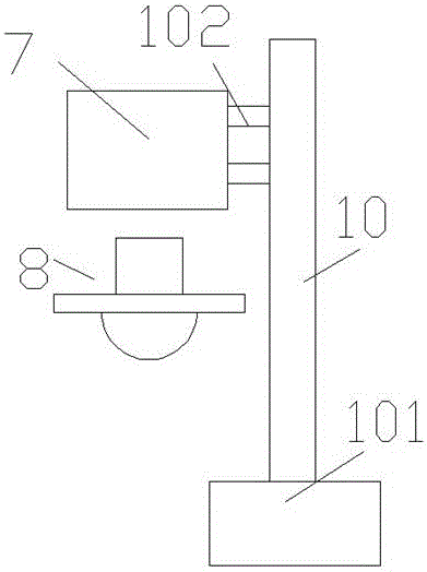
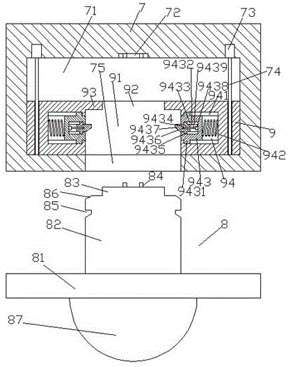
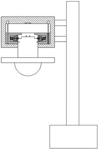
[0018] Such as Figure 1-Figure 6 As shown, a bridge monitoring device of the present invention includes a top base 7 and an insertion portion 8, the right side of the top base 7 is provided with a pillar 10, and the bottom of the pillar 10 is fixedly provided with a support seat 101, and the pillar 10 is provided with a strut 102 on the left side of the upper end, and the end of the strut 102 away from the strut 10 is fixedly connected with the right end surface of the top seat 7, and the top seat 7 is provided with a cavity 71, the cavity The inner top wall of cavity 71 is provided with spring insertion hole 72, and the inner top wall of described cavity 71 on both sides of described insertion spring hole 72 is provided with first motor 73 commensurately, each described first motor 73 bottoms Both are connected with a first screw rod 74, and the first screw rod 74 is threadedly connected with an assembly block 9, and the middle end of the assembly block 9 is provided with an...


PUM


Abstract

The invention discloses a bridge monitoring equipment comprising a top seat and an inserting part. A supporting column is arranged on the right side of the top seat. A supporting seat is fixedly arranged at the bottom of the supporting column. A supporting rod is arranged on the left side of the supporting column. One end, far from the supporting column, of the supporting rod is fixedly connected with the end face of the right side of the top seat. A cavity is formed in the top seat. An insert spring hole is formed in the inner top wall of the cavity. First motors are symmetrically arranged on the inner top wall, on the two sides of the insert spring hole, of the cavity. A first spiral rod is connected to the bottom of each first motor. The first spiral rods are connected with an assembling block in a threaded fit mode. An inserting groove is formed in the middle end of the assembling block. A baffle is arranged at the top end of the inserting groove. A through hole is formed in the middle end of the baffle. A guiding groove is formed in the bottom wall, opposite to the bottom of the inserting groove, of the top seat. First sliding cavities are symmetrically formed in the interior, on the two sides of the inserting groove, of the assembling block. First sliding grooves are symmetrically formed in the upper and lower inner side walls of each first sliding cavity.

Description

technical field [0001] The invention relates to the technical field of monitoring equipment, and particularly designs a bridge monitoring camera device. Background technique [0002] At present, surveillance cameras monitoring and filming violating vehicles can often be seen on some bridges. When the existing monitoring camera is installed, the camera is usually directly fixed on the pole by screws and then powered by an external line. When the camera fails and needs to be repaired, it must be disassembled by a screwdriver. It is cumbersome, time-consuming, labor-intensive and inefficient. At the same time, because the external circuit of the camera is exposed to the outside world, short-circuit faults are prone to occur in rainy days, which affects normal work and easily induces electric shock accidents, posing a greater safety hazard. Contents of the invention [0003] The technical problem to be solved by the present invention is to provide a bridge monitoring device, ...

Claims


Application Information

Patent Timeline
IPC IPC(8): F16M11/04
CPCF16M11/04
Inventor 陈佳佳
Owner 湖南长信建设集团有限公司
Why Eureka
Try Eureka