
Test tool support

A technology of checking fixtures and chassis, which is applied in the field of checking fixture manufacturing, can solve problems such as the difficulty of adjusting the checking fixture bracket, and achieve the effect of solving difficult adjustments

Inactive Publication Date: 2017-05-31
TIANJIN YIWEISHENG TECH CO LTD
View PDF0 Cites 0 Cited by
  • Summary
  • Abstract
  • Description
  • Claims
  • Application Information

AI Technical Summary

Problems solved by technology

[0005] The patent of the present invention provides a checking fixture bracket to solve the problem of difficult adjustment of the checking fixture bracket proposed in the above-mentioned background technology

Method used


Image

  • Test tool support

Examples


Embodiment

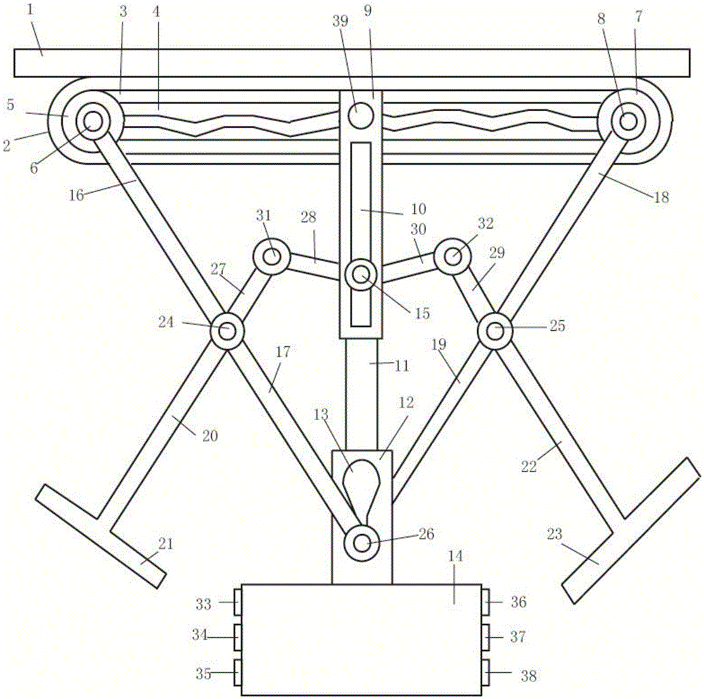
[0019] This embodiment includes a wear-resistant connecting plate 1, a checker bracket 2, a sliding groove 3, a zigzag slideway 4, a limiting plate A5, a fixed shaft A6, a limiting plate B7, a fixed shaft B8, a sliding shaft 9, and a stretching ruler slide Road 10, stretching ruler 11, lock 12, lock hole 13, fixed base 14, stretching ruler positioning bolt 15, connecting frame A16, connecting frame B17, connecting frame C18, connecting frame D19, stretching frame A20, fixing Handle A21, stretching frame B22, fixed handle B23, fixed shaft C24, fixed shaft D25, fixed shaft E26, connecting frame E27, connecting frame F28, connecting frame G29, connecting frame H30, fixed shaft F31, fixed shaft G32, limit Slot A33, limiting groove B34, limiting groove C35, limiting groove D36, limiting groove E37, limiting groove F38, sliding shaft positioning pin 39, sliding groove 3 is inside the checking fixture bracket 2, and zigzag slideway 4 is inside Inside the sliding groove 3, the sliding...


PUM


Abstract

The invention relates to a test tool support, and belongs to the field of test tool manufacture. The test tool support comprises a wear-preventive spacing groove, a test tool support body, a sliding groove, a zigzag slideway, a limiting plate A, fixing shafts A to G, a limiting plate B, a sliding shaft, a tensile rule slideway, a tensile rule, a lock, a lockhole, a fixing underframe, a tensile rule positioning bolt, connecting racks A to H, a tensile rack A, a fixing handle A, a tensile rack B, a fixing handle B, limiting grooves A to F, and a sliding shaft positioning bolt; and the sliding groove is arranged in the test tool support body, the zigzag slideway is in the sliding groove, the sliding shaft is arranged on the sliding groove, and the sliding shaft positioning bolt penetrates the sliding shaft.

Description

technical field [0001] The patent of the invention belongs to the field of inspection fixture manufacturing, and in particular relates to a inspection fixture bracket. Background technique [0002] Inspection fixture is the abbreviation of online inspection and inspection fixtures such as stamping parts and welding parts, and has the same meaning as the sample holder mentioned in other documents. The inspection tool is a kind of inspection tool specially manufactured according to the specific requirements of the buyer. The shape and surface of the inspection tool must be milled according to the CAD data of the part, which can reflect all the parameters of the part and perform qualitative inspection on the part. For some extremely important functional dimensions on parts, numerical testing can also be carried out by using checking tools. The inspection tool should also have the function of measuring support, but when the online detection function of the inspection tool and ...

Claims


Application Information

Patent Timeline
Patent Type & Authority Applications(China)
IPC IPC(8): G01B21/00
CPCG01B21/00
Inventor 任敬
Owner TIANJIN YIWEISHENG TECH CO LTD
Learn More