
An automatic test system for sensor working area

An automatic test system, work area technology, applied in radio wave measurement systems, instruments, measurement devices, etc., can solve problems such as low work efficiency and manpower consumption

Active Publication Date: 2018-09-14
B E A ELECTRONICS BEIJING
View PDF4 Cites 0 Cited by
  • Summary
  • Abstract
  • Description
  • Claims
  • Application Information

AI Technical Summary

Problems solved by technology

Every time a sensor working area test is completed, the tester needs to walk around many times, which consumes a lot of manpower and reduces work efficiency

Method used


Image

  • An automatic test system for sensor working area
  • An automatic test system for sensor working area
  • An automatic test system for sensor working area

Examples


Embodiment Construction

[0048] In order to make the object, technical solution and advantages of the present invention clearer, the present invention will be further described in detail below in conjunction with the accompanying drawings. It should be understood that the specific embodiments described here are only used to explain the present invention, not to limit the present invention.

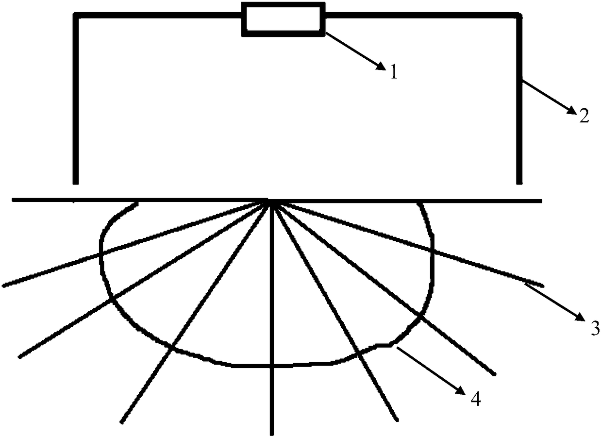
[0049] Such as figure 1 As shown, the existing microwave sensor working area testing method is as follows: the sensor to be tested 1 is installed on the bracket 2, and the position of the sensor to be tested 1 is pre-adjusted and controlled by the bracket 2. Then, the tester or the test body approaches the sensor along the test travel route 3, and other testers are responsible for recording the position when the tester triggers the sensor. Finally, by changing the test route 3 at different angles, the working area of ​​the sensor is summarized Figure 4 . This method requires a lot of manpower and time costs, a...


PUM


Abstract

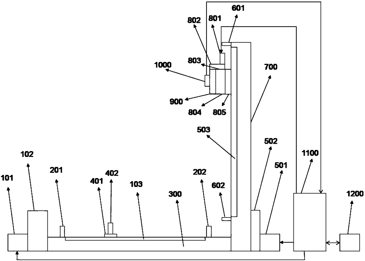
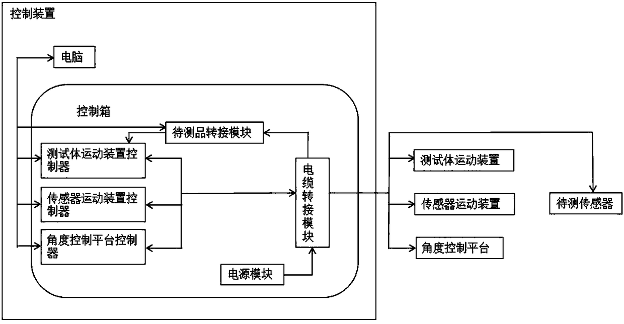
To solve the defect of the conventional sensor working area test, the invention provides a sensor working area automatic test system. The system comprises a test body movement device, a sensor movement device and a control device. The test body movement device is used for installing and controlling a test body, and the device controls the test body to move in a region to be tested in a given moving posture under a command of the control device; the sensor movement device is used for installing and controlling a sensor to be tested, and the device controls the sensor to be tested to detect the test body in the region to be tested in given detection conditions under a command of the control device, and sends the feedback data to the control device; and the control device controls the moving posture of the test body and the detection conditions of the sensor to be tested according to the commands sent by a user, and processes the received feedback data sent by the sensor to be tested into data in a user-predefined expression form.

Description

technical field [0001] The invention relates to an automatic test system for a working area of ​​a sensor, in particular to the field of testing the working area of ​​a microwave sensor. Background technique [0002] Microwave sensor is a device that uses microwave characteristics to detect some physical quantities. It is an active detection technology that uses the Doppler effect related to the frequency change of the reflected wave and the moving speed of the emitting object to detect the motion of the object. This product is widely used in automatic doors. Normally, the automatic door is kept closed. When a moving object enters the working area of ​​the microwave sensor, the microwave sensor detects the moving object and sends a control signal to open the door. [0003] The current sensor working area test method is: the sensor is installed at a fixed height, the tester moves towards the sensor from different directions, records the trigger position of the sensor and manu...

Claims


Application Information

Patent Timeline
Patent Type & Authority Patents(China)
IPC IPC(8): G01S13/88G01S7/02
CPCG01S7/02G01S13/88
Inventor 徐玉河杨雪
Owner B E A ELECTRONICS BEIJING
Learn More