Method and device for dynamometer testing of a motor vehicle

a technology of dynamometer and motor vehicle, which is applied in the direction of engine testing, structural/machine measurement, instruments, etc., can solve the problems of not always being able to provide the desired measurement accuracy and/or measurement freedom

Active Publication Date: 2011-12-15
ROTOTEST INT
View PDF7 Cites 34 Cited by
  • Summary
  • Abstract
  • Description
  • Claims
  • Application Information

AI Technical Summary

Problems solved by technology

Such systems, however, are not always capable of providing the desired measurement accuracy and/or measurement freedom.
There exist, however, situations where measurement results representing a true vehicle

Method used


Image

  • Method and device for dynamometer testing of a motor vehicle
  • Method and device for dynamometer testing of a motor vehicle
  • Method and device for dynamometer testing of a motor vehicle

Examples


Embodiment Construction

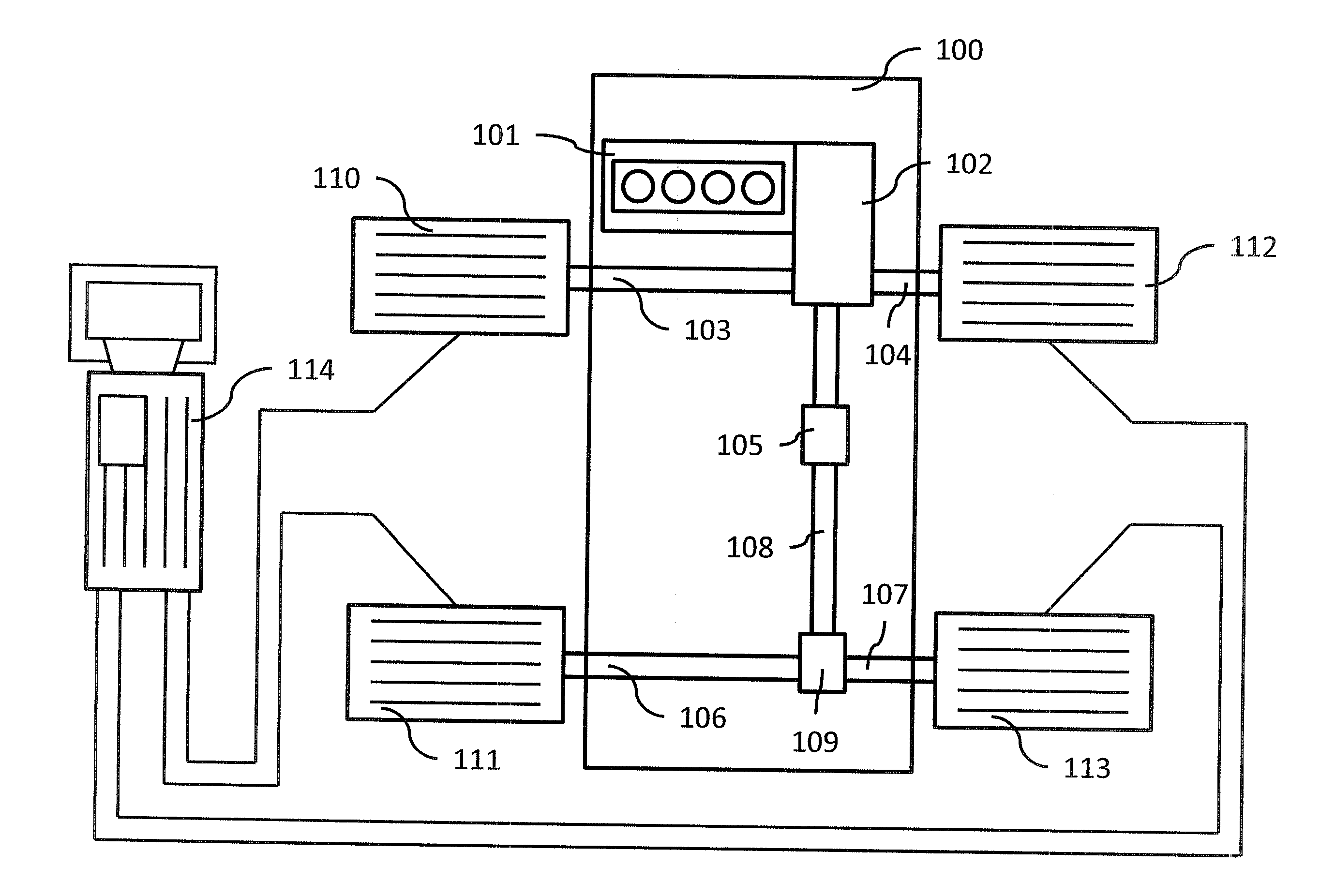
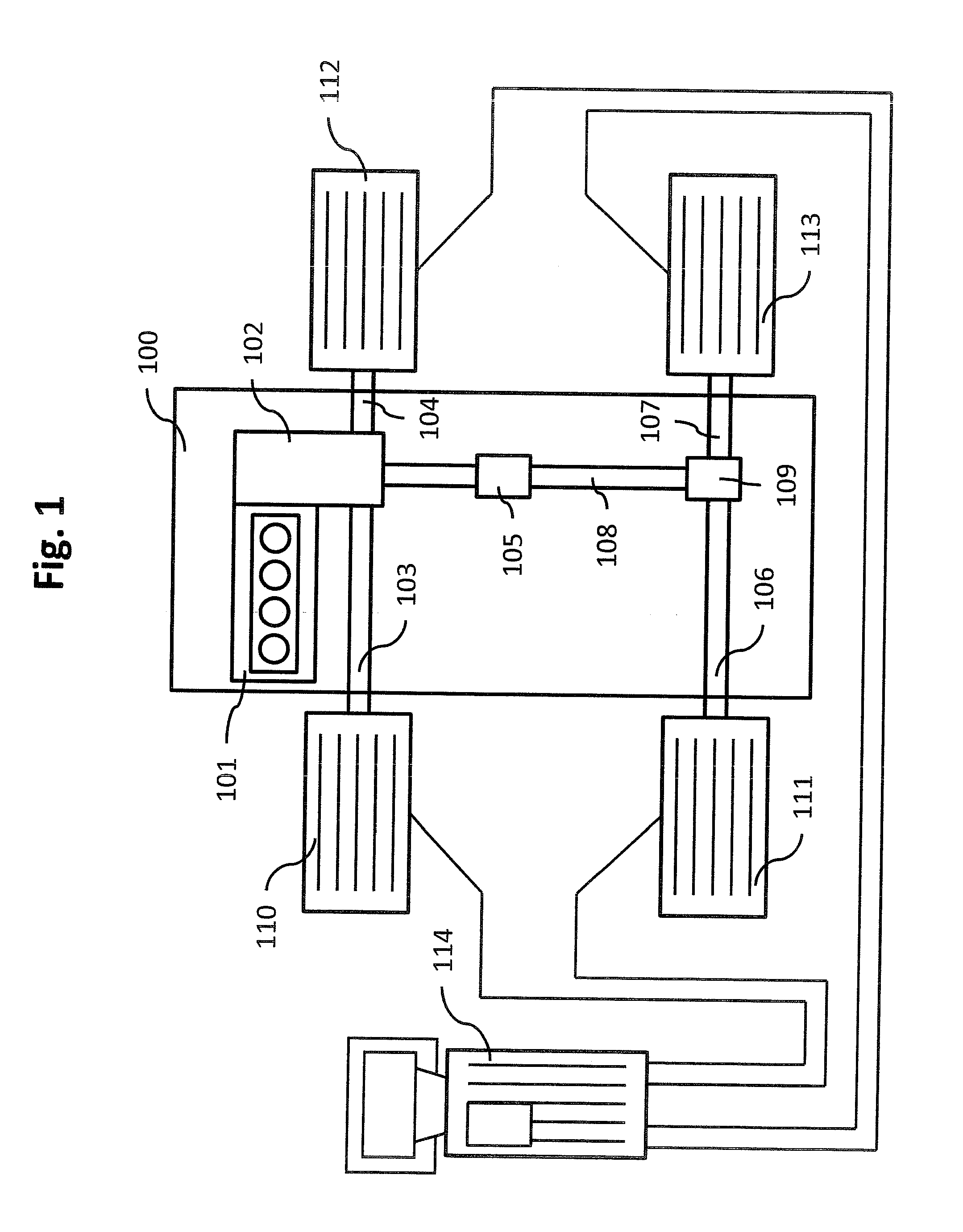
[0035]FIG. 1 discloses a vehicle 100 in the process of being tested with a vehicle dynamometer testing system according to the prior art.

[0036]The disclosed vehicle 100 comprises a drive train, which comprises a combustion engine 101 which, in a conventional manner, is connected to a gearbox 102. The gearbox 102 can be of any suitable kind and, e.g., consist of a manual transmission or an automatic transmission.

[0037]The vehicle 100 is a four-wheel drive vehicle, and comprises front axle wheel shafts 103, 104, and rear axle wheel shafts 106, 107. The vehicle further comprises a torque distributor 105 for distributing the torque (power) provided by the combustion engine 101 (via the gear box 102) to the front axle wheel shafts 103, 104 and the rear axle wheel shafts 106, 107 of the vehicle. A propeller shaft 108 connects the torque distributor 105 with the rear axle wheel shafts 106, 107 via a final drive 109. The wheels of the vehicle are not shown due to the vehicle being set up fo...


PUM


Abstract

The present invention relates to dynamometer testing of a vehicle comprising at least a first wheel shaft and a second wheel shaft and a first power source for providing power to said first wheel shaft. The method comprises, with only said first wheel shaft being connected to a dynamometer test unit,
    • applying a first power to said first wheel shaft,
    • determining a representation of said first power by means of said dynamometer test unit,
    • determining a second power, being different from said first power, to be applied to at least one of said first wheel shaft and said second wheel shaft, the said second power being a virtual power being represented by a virtual representation of said second power, and
    • by means of the representation of said first power determined by said dynamometer test unit and said virtual representation of said second power, determining a first speed being a representation of the speed of said vehicle when being driven on a road subjected to said first and second power.

Description

[0001]This application claims the benefit of U.S. Provisional Application Ser. No. 61 / 354,431, filed Jun. 14, 2010, the disclosure of which is incorporated by reference.FIELD OF THE INVENTION [0002]This invention relates to dynamometer testing of vehicles, and in particular to a method and a device for dynamometer testing of vehicles.BACKGROUND OF THE INVENTION[0003]Dynamometer testing of vehicles is known per se, and can, for example, be carried out by roller type dynamometers equipped with large rollers that support the vehicle wheels, and which are used to apply a brake torque to the drive wheels of the vehicle. Such systems, however, are not always capable of providing the desired measurement accuracy and / or measurement freedom.[0004]Another kind of vehicle dynamometers for dynamometer testing of vehicles is disclosed in U.S. Pat. No. 4,669,318 (Angstrom). This document relates to an apparatus for dynamometer testing of motor vehicles, where load absorbing means in the form of a...

Claims


Application Information

Patent Timeline
IPC IPC(8): G01M17/007
CPCG01M17/0074
Inventor ENGSTROM, CHRISTIAN
Owner ROTOTEST INT
Why Eureka
Try Eureka