Testing method for complex dielectric permittivity of multi-mould in one chamber, wide-frequency and multi-point microwave medium

A technology of complex permittivity and microwave medium, which is applied in the field of microwave technology and electronics, and can solve problems such as troubleshooting and automatic search

Inactive Publication Date: 2003-03-26
UNIV OF ELECTRONICS SCI & TECH OF CHINA
View PDF1 Cites 37 Cited by
  • Summary
  • Abstract
  • Description
  • Claims
  • Application Information

AI Technical Summary

Problems solved by technology

[0004] As far as the inventor knows, the unresolved problems in the existing documents and test methods are: (1) without changing the cavity size, the polarization direction of the electric field is parallel to the sample surface, and the broadband complex permittivity test is performed; (2) ) In one to two octave wide frequency bands, the identification of cavity modes; (3) In the wide frequency band, under the condition of multiple resonance frequencies, after loading the dielectric sample, the problem of automatic mode finding; (4) Wide frequency band Internal, interference pattern exclusion issues

Method used


Image

  • Testing method for complex dielectric permittivity of multi-mould in one chamber, wide-frequency and multi-point microwave medium
  • Testing method for complex dielectric permittivity of multi-mould in one chamber, wide-frequency and multi-point microwave medium
  • Testing method for complex dielectric permittivity of multi-mould in one chamber, wide-frequency and multi-point microwave medium

Examples


Embodiment Construction

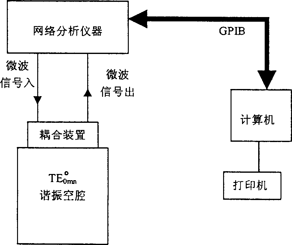
[0056] The embodiment of the present invention is designed according to the first step of the scheme of the present invention, and the cavity dimensions of the 2-7GHz cavity (ie, the large cavity) and the 7-18GHz cavity (ie, the small cavity) can be obtained respectively; the test of the complex dielectric constant see process Figure 5 ; All operations are automatically tested by computer program control.

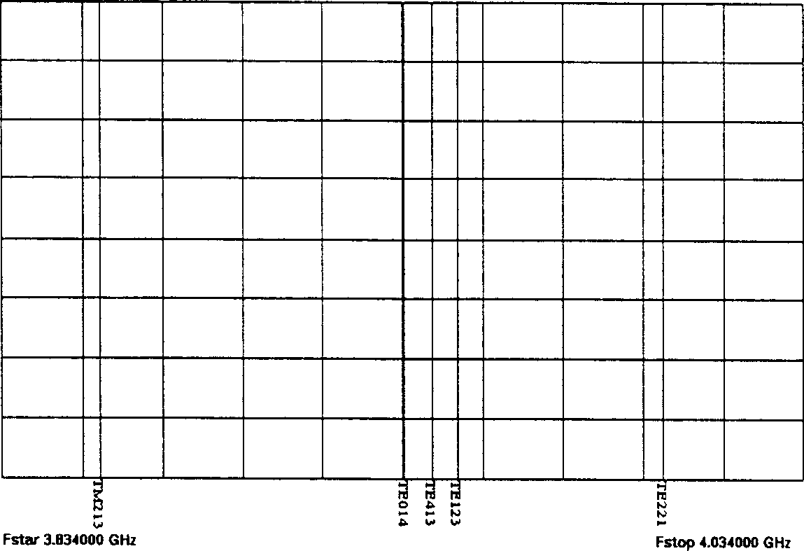
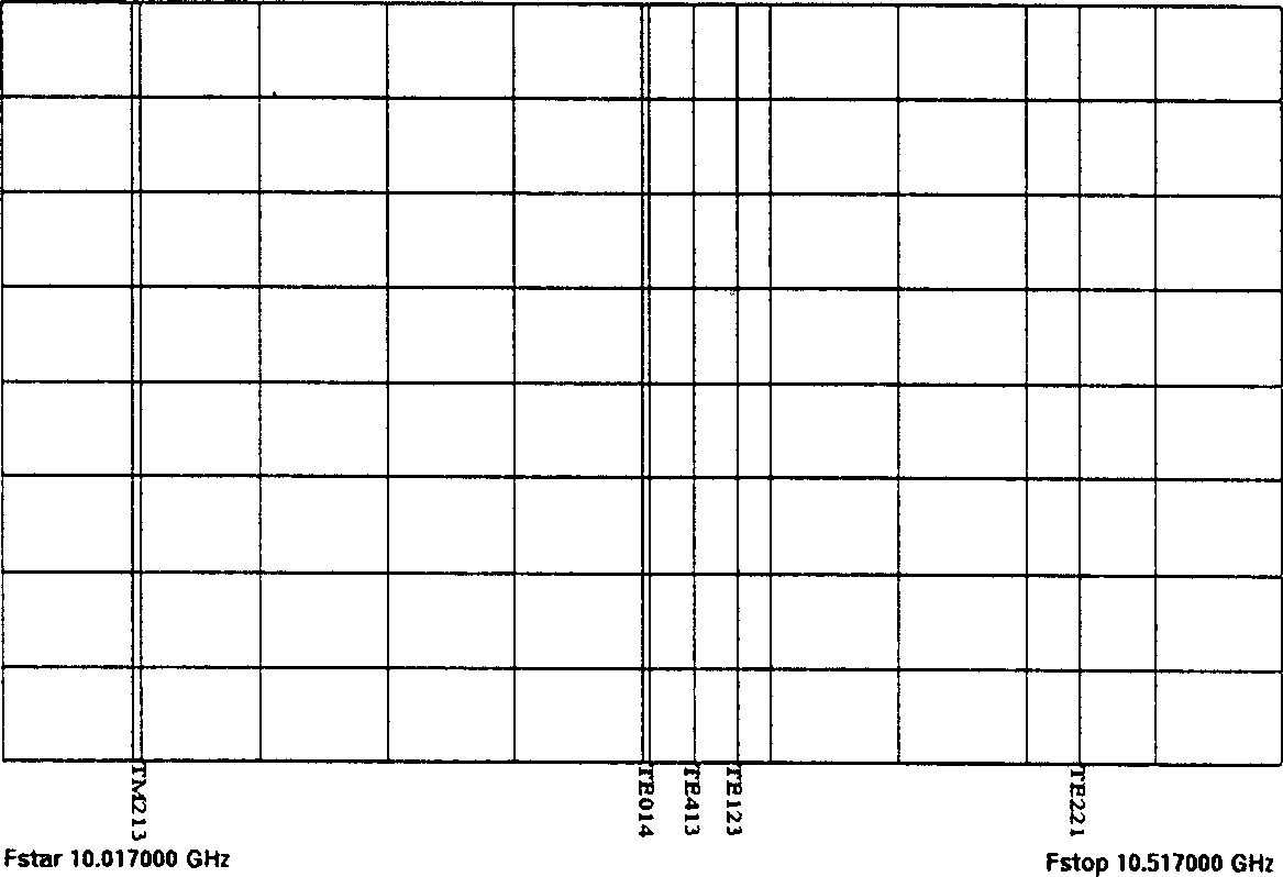
[0057] Using the present invention, the cavity and several samples were tested separately. to TE 014 mode as an example, the resonant frequency distribution and resonant curve of the cavity are shown in Figure 6-9 , due to the rationally designed coupling method in the coupling device, some undesired modes are suppressed; comparefigure 1 with Image 6 , figure 2 with Figure 8 It can be seen that, except for the adjacent mode resonance which is successfully suppressed due to too weak coupling, the theoretically calculated resonance frequency distribution is consiste...


PUM


Abstract

This invention provides a test method for one cavity multiple modes broad-band multiple points microwave medium multiple dielectric constants. By designing and producing a "clean" multiple frequency points, high Q cylindrical test resonance chamber of broad band and internal mould type, the method finishes identifying each target mode in the hollow resonator, thereto obtain the equivalent "cavity dimensions" of the required mode in the cavity and zero load quantity factor Q0. As for the resonantor loaded with medium, it uses test results by modes necessary for sublevel to compute frequencies of each interfered target mode finishing automatic search of resonate frequency of different modes after being interfered to test the resonate frequency of sample after loading and zero load quality factor Q0, finally, finishing test to multiple dielectric constants of different frequency according to the tested data.

Description

Technical field: [0001] The invention belongs to the field of electronic technology, in particular to the field of microwave technology. Background technique: [0002] As we all know, the dielectric microwave complex permittivity is the basis for the accurate design and manufacture of microwave components, microwave antennas and radomes. At the same time, the complex permittivity of materials is also an important parameter for studying the electrical properties of materials. It is of great significance to accurately test the electrical constant. [0003] For microwave wave-transparent materials-low-loss dielectric testing techniques, there are high-Q cavity method, stripline method, perturbation method, etc. Different methods should be used for different sample shapes and electric field polarization directions. The high-Q cavity method is to use TE 0mn High Q Cylindrical Cavity (TE 0mn High Q Cylindrical Cavity) is used as a test chamber to test the microwave complex pe...

Claims


Application Information

Patent Timeline
Patent Type & Authority Applications(China)
IPC IPC(8): G01R27/26
Inventor 郭高凤李恩张其劭
Owner UNIV OF ELECTRONICS SCI & TECH OF CHINA
Why Eureka
Try Eureka