Method of repairing non-uniform degradation of detector

A repair method and non-uniformity technology, applied in the field of infrared imaging, can solve problems such as non-uniformity, restricting the performance of IRFPA imaging systems, non-uniformity, etc., and achieve the effect of solving repair problems

Active Publication Date: 2017-05-31
TIANJIN XITONG ELECTRONICS EQUIP CO LTD
View PDF6 Cites 4 Cited by
  • Summary
  • Abstract
  • Description
  • Claims
  • Application Information

AI Technical Summary

Problems solved by technology

However, there is generally inconsistency among the response characteristics of each detection unit of IRFPA, that is, the non-uniformity of the response
This inherent problem will cause different degr

Method used


Image

  • Method of repairing non-uniform degradation of detector
  • Method of repairing non-uniform degradation of detector
  • Method of repairing non-uniform degradation of detector

Examples


Embodiment Construction

[0036] In order to make the purpose, content, and advantages of the present invention clearer, the specific implementation manners of the present invention will be further described in detail below in conjunction with the accompanying drawings and embodiments.

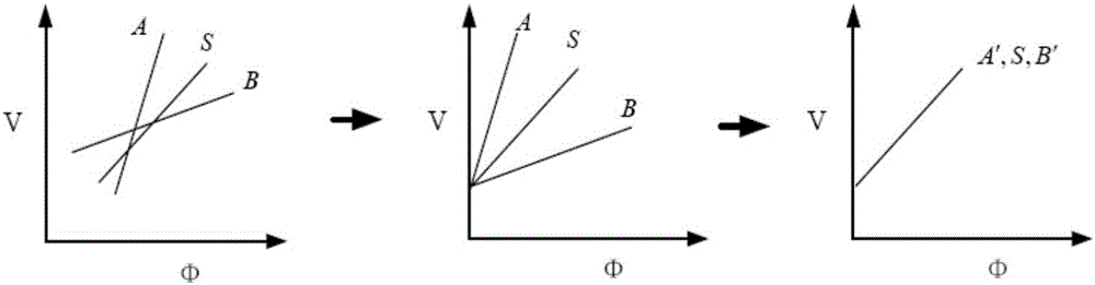
[0037] In order to solve the above technical problems, the present invention provides a detector non-uniformity degradation repair method, which improves the multi-integration time multi-segment two-point correction method, removes the influence of the detector response drift on the correction parameters, and solves the problem of detector degradation problem, including the following steps:

[0038] Step 1: Generate correction parameters;

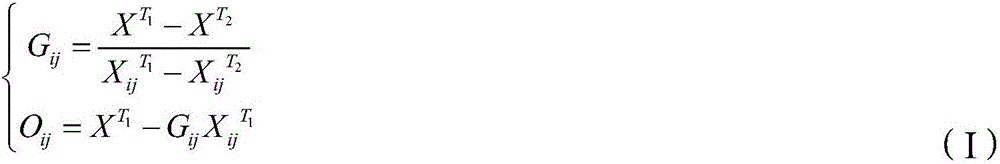
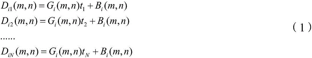
[0039] Step 101: Calculate the fixed response offset of the detector;

[0040] Set N integration times I 1 , I 2 ,..., I N , collect M blackbody temperatures T 1 , T 2 ,...,T M The detector response data are D 11 、D 12 …D 1N …D MN ; where D 11 is the integration time for I...


PUM


Abstract

The invention belongs to the technical field of infrared imaging and particularly relates to a method of repairing non-uniform degradation of a detector. Compared with the prior art, the invention is intended to provide a method of repairing non-uniform degradation due to detector response drift, particularly non-uniformity technique, detector response fixed offset removal technique, and detector integral time normalization technique. Integral time normalization non-uniformity correction parameter of detector response fixed offset is calculated and removed, the impact of detector response drift upon the correction parameter is removed, fixed offset due to detector drift is calculated each time after the detector is powered up, the acquired detector fixed offset is removed during correction, real-time correction is performed via integral time normalization algorithm, and non-uniform degradations of other integral time are repaired via pre-correction method during integral time switching.

Description

technical field [0001] The invention belongs to the technical field of infrared imaging, and in particular relates to a detector non-uniformity degradation repair method, in particular to a non-uniformity correction technology, a detector response fixed offset removal technology and a detector integration time normalization correction technology. Background technique [0002] The infrared focal plane array imaging system represents the development direction of a new generation of infrared imaging systems. Compared with other thermal imaging systems, it has many advantages such as simple structure, high reliability, high detection sensitivity and high working frame frequency, and has broad application prospects. However, there is generally inconsistency among the response characteristics of IRFPA detection units, that is, the non-uniformity of the response. This inherent problem will cause varying degrees of fixed pattern noise interference on the imaged image, obliterating t...

Claims


Application Information

Patent Timeline
IPC IPC(8): G01J5/20
CPCG01J5/20G01J2005/202G01J2005/0077G01J5/80
Inventor 毛贵超张志恒
Owner TIANJIN XITONG ELECTRONICS EQUIP CO LTD
Why Eureka
Try Eureka