
Detection device and method of detecting ammonia gas by utilizing photo-acoustic spectroscopy method

A technology of photoacoustic spectroscopy and gas detection, which is used in measurement devices, color/spectral property measurement, and material analysis by optical means. and other problems to achieve the effect of eliminating signal interference, efficient collection, and accurate concentration results

Pending Publication Date: 2017-05-31
江苏舒茨测控设备股份有限公司
View PDF7 Cites 14 Cited by
  • Summary
  • Abstract
  • Description
  • Claims
  • Application Information

AI Technical Summary

Benefits of technology

This patented technique involves combining photonics techniques (photoacoupling) with infarction detection methods like laser absorption spectrometry or near field imaging. By doing these technologies together, it allows for efficient collection of tiny amounts of gases such as nitrogen oxynitride NO2/NH, hydrocarbons, oxygen, etc., while also eliminating any unwanted noise from other sources. These technical improvements make them ideal tools for various applications including environmental monitoring, industrial processes, medical diagnosis, and biological researches.

Problems solved by technology

Technological Problem addressed in this patents relate to the monitoring of minute levels of volatile organosulfur chemicals called urea or formaldehydes in ambient environments like homes' houses where humans live. Current techniques involve analyzers that require frequent replacement due to contamination from exhaust products and human activities. There currently exist nonreactive ionization mass spectrometry systems, including atomic emission spectroscopy and laser scattering instruments. However these current technologies lack specificity and precision required for accurate measurements over wide range of analyte values. Therefore there remains a challenge in accurately measuring small quantities of harmful materials in realistic spatially distributed locations without interferring with normal living conditions.

Method used


Image

  • Detection device and method of detecting ammonia gas by utilizing photo-acoustic spectroscopy method
  • Detection device and method of detecting ammonia gas by utilizing photo-acoustic spectroscopy method
  • Detection device and method of detecting ammonia gas by utilizing photo-acoustic spectroscopy method

Examples


Embodiment 1

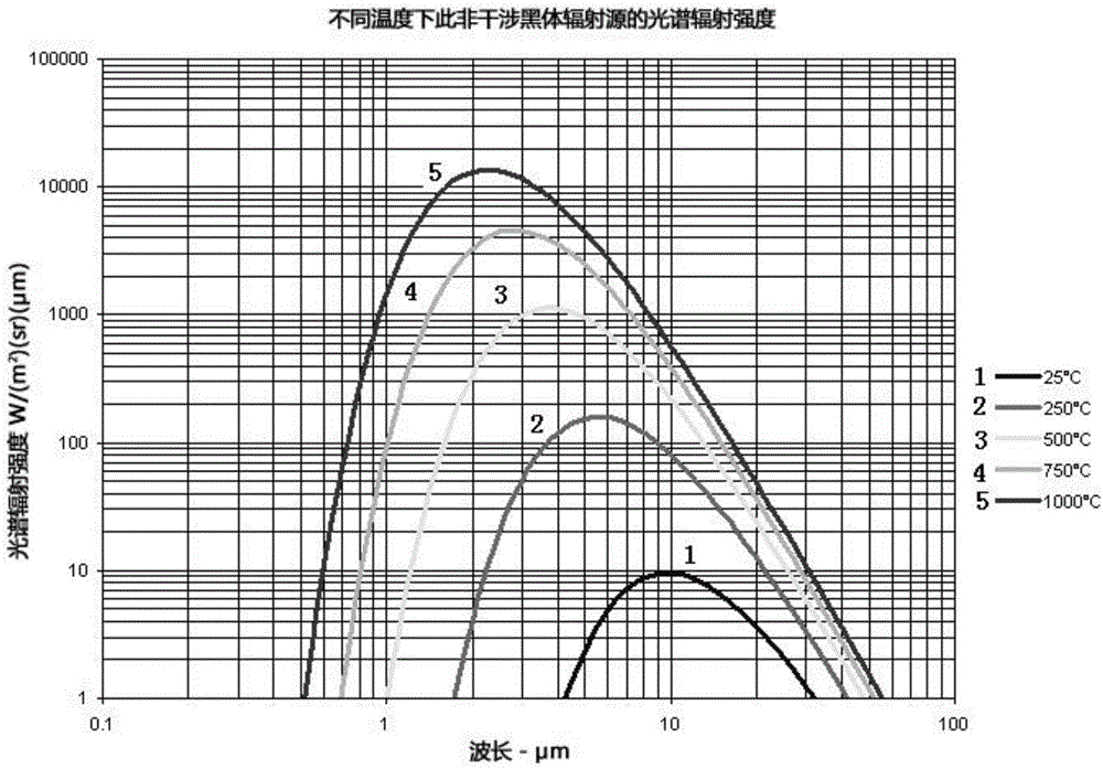
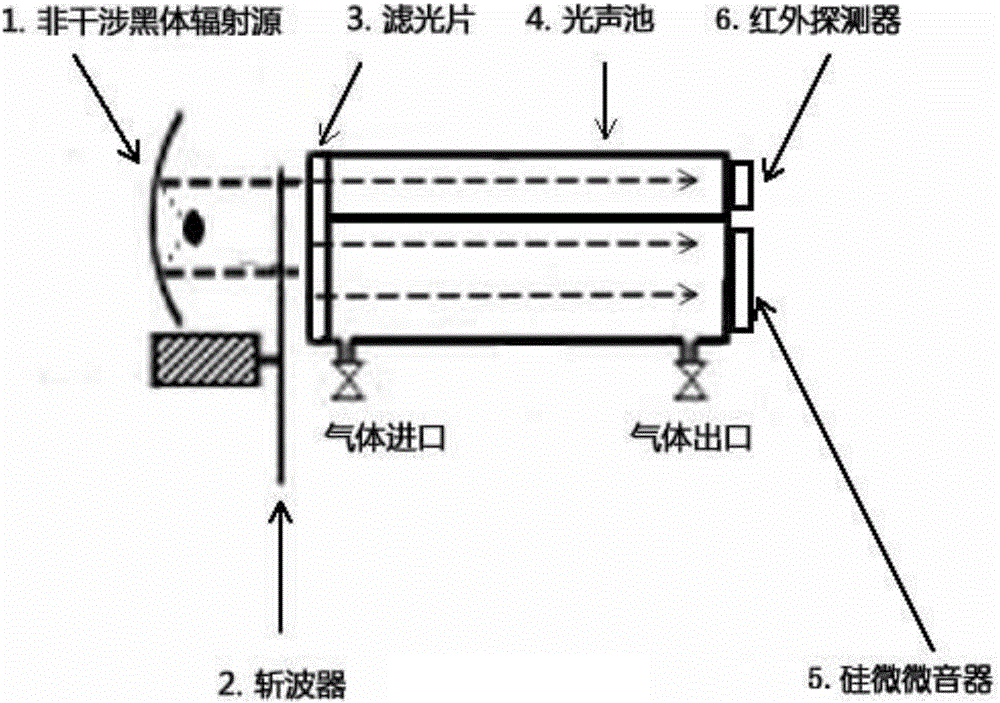
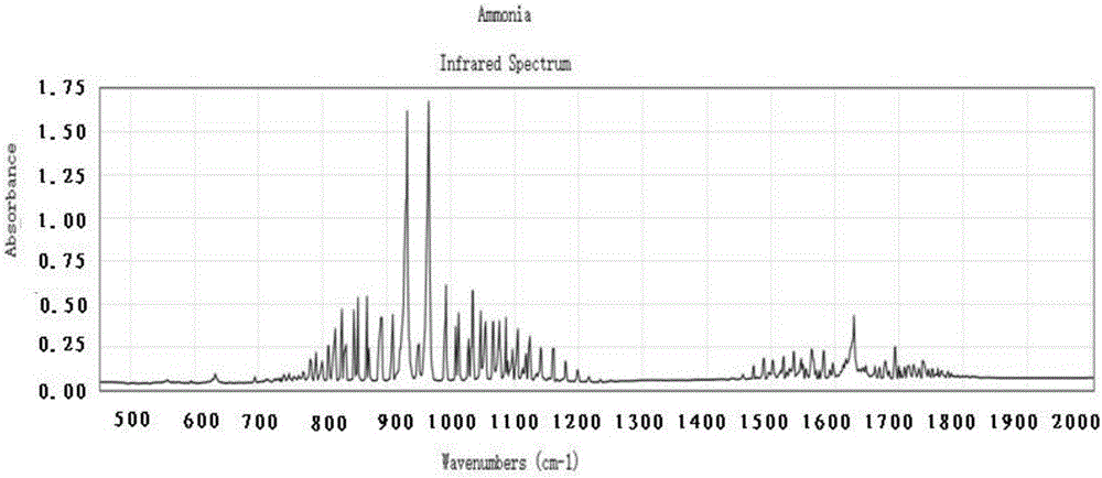
[0040]Using a non-interfering thermal radiation source as the light source 1, together with a narrow-band filter with a center wavelength of 10.2 microns and a wave number of 937 and a mechanical chopper, monochromatic light with adjustable intensity is irradiated into the sealed photoacoustic cell 4 . The photoacoustic cell 4 is divided into two air chambers, the upper air chamber is equipped with an infrared detector 6 on the right side; the lower air chamber is equipped with a silicon picophone 5 . The gas molecules in the lower part of the photoacoustic cell 4 are excited after absorbing electromagnetic radiation, and transition to a higher excited state. The electronic, vibrational and rotational states of molecules are all quantized. Usually, gas molecules return to the ground state by emitting fluorescence or vibrating. The vibration causes the temperature of the gas to rise and transfer energy, which is called non-radiative relaxation. The premise of this non-radiativ...


PUM

PropertyMeasurementUnit
Center wavelengthaaaaaaaaaa
The inside diameter ofaaaaaaaaaa

Abstract

The invention discloses a detection device and method of detecting ammonia gas by utilizing a photo-acoustic spectroscopy method. The detection device comprises a light source, a chopper, an optical filter, a photoacoustic cell, a micro-silicon microphone and an infrared detector; the chopper is arranged in parallel in front of the photoacoustic cell; the optical filter is arranged at the left end of the photoacoustic cell; the photoacoustic cell is divided into an upper air chamber and a lower air chamber; the infrared detector is embedded in the right end of the air chamber at the upper part; the micro-silicon microphone is embedded in the right end of the air chamber at the lower part; the infrared detector and the micro-silicon microphone are arranged on a same vertical plane; and light from the light source is input into the optical filter and filtered by the optical filter and then enters the photoacoustic cell after being subjected to wave chopping by the chopper. According to the detection device and method, the photoacoustic cell is divided into the upper air chamber and the lower air chamber, and the micro-silicon microphone and the infrared detector are arranged in parallel on the same side of the upper air chamber and the lower air chamber from top to bottom respectively, so that the micro-silicon microphone and the infrared detector carry out detection at the same time; and on signal detection, the micro-silicon microphone and the infrared detector generate signals in the same light source and a gas cavity at the same time, and interference is calculated and rejected, so that a final concentration result is more accurate.

Description


Claims


Application Information

Patent Timeline
Owner 江苏舒茨测控设备股份有限公司
Learn More