Lens driving device

A lens driving device and lens technology, applied in installation, instrumentation, optics, etc., can solve the problems of difficult size control, easy warping and deformation of the outer edge of the coil, and difficulty in wire routing, and achieve the effect of low process requirements.

Pending Publication Date: 2017-05-31
HUIZHOU SAGETECH OPTRONICS CO LTD
10 Cites 5 Cited by

AI-Extracted Technical Summary

Problems solved by technology

However, when the coil is made by directly winding the coil on the convex posts on both sides of the lens holder, the outer edge of the coil is prone to warping and deformation, and the size is difficult to control
In addition, it is also possib...

Method used

The lens driving device of the present invention modularizes the coil—directly forms a printed coil on two circuit boards, attaches the circuit board to both sides of the lens holder, and then electrically conducts the coil through the conductive terminal on the circuit board and the...

Abstract

The invention relates to a lens driving device. An electromagnetic driving mechanism of the lens driving device includes two circuit boards and two magnet modules, wherein the two circuit boards are attached to the periphery side of a lens mount, and the two magnet modules are fixed on the inner side of a box body. The two circuit boards are arranged in a back-to-back mode, and one or more printed coils are formed on each circuit board. The magnetic modules are opposite to and separated from the printed coils on the two circuit boards respectively. Two or more conductive terminals extend from each circuit board towards a spring component and make electric contact with the spring component, and therefore the spring component serves as a conductive path of the electromagnetic driving mechanism. According to the lens driving device, two sides of the lens mount are directly attached with the circuit boards with the printed coils, and by the conductive terminals which extend from circuit boards towards the spring component and make electric contact with the spring component, the routing and power-supply problems between the two coils are solved, and the device is easy to manufacture and implement, and low in technological requirement.

Application Domain

Mountings

Technology Topic

MagnetElectricity +3

Image

  • Lens driving device
  • Lens driving device

Examples

  • Experimental program(1)

Example Embodiment

[0014] The lens driving device of the present invention will be described in further detail below with reference to specific embodiments and accompanying drawings.
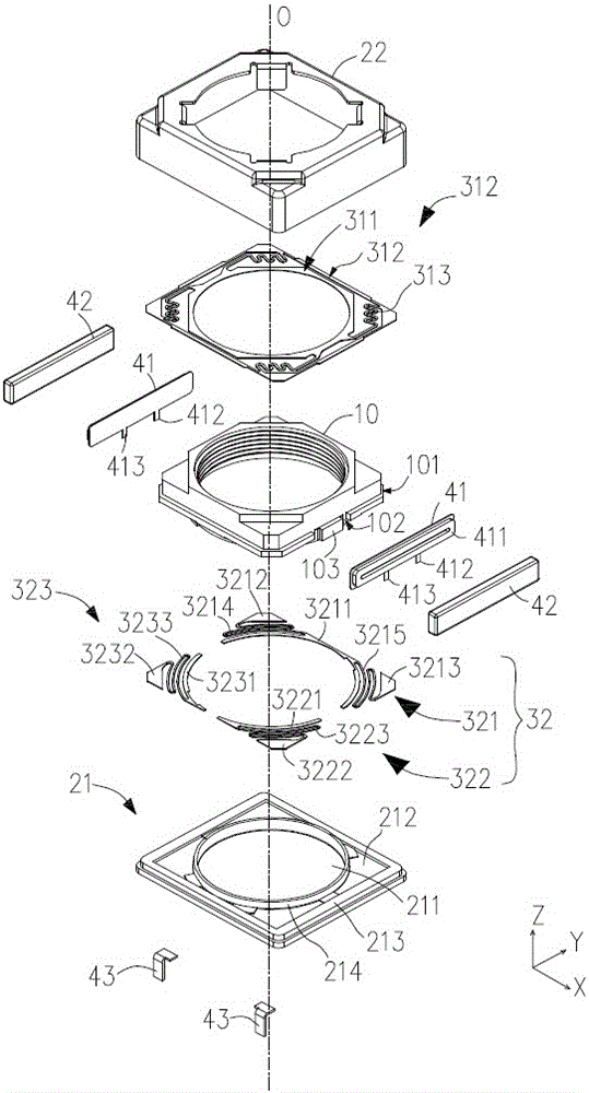
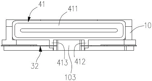
[0015] like figure 1 and figure 2 As shown, in a preferred embodiment, the lens driving device of the present invention mainly includes a lens holder 10 for holding an unillustrated lens, a base 21 and a front cover 22 that is fastened on the base 21. A case, a spring member for suspending the lens holder 10 on the case and enabling it to move in the optical axis direction O of the lens, and an electromagnetic drive mechanism 40 for driving the lens holder to move in the optical axis direction of the lens.
[0016] Hereinafter, in this specification, the optical axis direction O of the lens is referred to as the Z-axis direction, and the subject side is referred to as the Z-axis front (+Z side or +Z direction). In addition, two axes which are orthogonal to each other and are orthogonal to the Z-axis, respectively, are used as the X-axis and the Y-axis.
[0017] The lens holder 10 is made of a resin material such as liquid crystal polymer or nylon, and is a square cylindrical member that holds a lens formed by combining an objective lens and an eyepiece on the inside. An opposing pair of the four outer side walls of the lens holder 10 is perpendicular to the X axis, and the other pair is perpendicular to the Y axis.
[0018] As mentioned above, the box body is composed of the base 21 and the front cover 22 fastened on the base 21 , and is also made of a resin material such as liquid crystal polymer or nylon, which is arranged on the lens holder 10 in a manner of surrounding the lens holder 10 . outside. The base 21 includes a square plate-shaped bottom plate 212 with an opening 211 formed in the center, a cylindrical side wall 213 extending vertically from the outer edge of the bottom plate 212 in the +Z direction, and from the inner edge of the opening 211 in the +Z direction. The annular restricting portion 214 extends vertically in the direction. The annular restricting portion 214 is used to restrict the lowest position of the lens holder 10 , and the position at which the electromagnetic drive mechanism 40 is not energized is taken as the rearmost position of the lens holder 10 .
[0019] The spring members include a front-side spring member 31 provided on the front side of the lens holder 10 and a rear-side spring member 32 provided on the rear side of the lens holder 10 . In this embodiment, the structures of the front side spring member 31 and the rear side spring member 32 are different, and the rear side spring member 32 not only acts as a spring, but also acts as a conductive path of the electromagnetic drive mechanism 40 . Therefore, the rear side spring member 32 is a leaf spring made of a conductive metal or alloy such as copper, nickel, tin, etc., while the front side spring member 31 may be formed of the same material as the rear side spring member 32, or may be made of a larger material than the rear side spring member 32. The member 32 can be made of other materials with better restoring force, such as rubber.
[0020] like figure 1 As shown, the front side spring member 31 includes: an annular inner holding portion 311 mounted on the front side of the lens holder 10, a square annular outer holding portion 312 mounted on the inner side of the front cover 22, and connected to the inner holding portion 311 and the outer side Four wrist portions 313 between the holding portions 312 . The wrist portion 313 extends from the outer edge of the inner holding portion 311 , firstly extending substantially parallel to the edge of the outer holding portion 313 , then extending substantially along the circumferential direction of the lens holder 10 , and finally connecting with the outer holding portion 312 .
[0021] In other embodiments, if the front side spring member is made of rubber or similar materials, it can be in the shape of a square sheet with a circular opening formed in the middle.
[0022] The rear-side spring member 32 includes a first portion 321 that is divided into independent (not in contact with each other), approximately one-half, and second and third portions 322 and 323 that are approximately one-quarter, respectively. As a whole, the rear side spring member 32 is also a square leaf spring with a circular opening in the center, which is divided into two along the X-axis direction, the half on the +Y side is the first part 321, and the half on the -Y side is the first part 321. The part of is divided into two parts along the Y-axis direction, the quarter part located on the +X side is the second part 322 , and the quarter part located on the -X side is the third part 323 . The rear spring member 32 includes arc-shaped inner holding parts 3211 , 3221 , 3231 installed on the rear end surface of the lens holder 10 , and outer holding parts 3212 , 3213 , 3222 , 3232 installed at the four corners of the bottom plate 212 of the base 21 . , and the wrist parts 3214 , 3215 , 3223 and 3233 connected between the inner holding parts 3211 , 3221 and 3231 and the outer holding parts 3212 , 3213 , 3222 and 3232 . The wrist portion 3214 is connected between the inner holding portions 3211 and the outer holding portions 3212 . The wrist portion 3215 is connected between the inner holding portion 3211 and the outer holding portion 3213 . The wrist portion 3223 is connected between the inner holding portion 3221 and the outer holding portion 3222 . The wrist portion 3233 is connected between the inner holding portion 3231 and the outer holding portion 3232 . In this embodiment, the wrist portions 3214 , 3215 , 3223 , and 3233 extend alternately in the circumferential direction and the radial direction of the lens holder 10 , respectively. In other embodiments, the wrist portions 3214 , 3215 , 3223 , and 3233 may extend in either or both of the circumferential direction and the radial direction.
[0023] Please also refer to figure 2 , the electromagnetic drive mechanism 40 includes two circuit boards 41 attached to the outer peripheral side of the lens holder 10 and two magnet modules 42 fixed on the inner side of the front cover 22 . Wherein, the two circuit boards 41 are disposed opposite to each other, and are respectively attached to the two outer sides of the lens holder 10 located in the X-axis direction. The circuit board 41 is in the shape of a square plate, and a rectangular annular printed coil 411 is formed in the middle thereof. The printed coil 411 may be a coil formed on the circuit board 41 by a semiconductor process or a pre-process, such as, but not limited to, etching or deposition. The long side of the printed coil 411 is parallel to the Y-axis direction. The two magnet modules 42 are respectively attached to the inner middle portions of the two side walls of the front cover 22 in the X-axis direction, and are arranged opposite to the printed coils 411 on the two circuit boards 41 in a space. It can be understood that, in order to drive the lens holder 10 to move along the Z-axis direction, each magnet module 42 includes two magnets (or one magnet with two magnet units) arranged up and down along the Z-axis direction. It is magnetized in the radial direction, and its magnetic pole faces face the printed coil 411 and have opposite polarities. The two magnets are respectively opposite to the two long sides of the printed coil 411 . In this way, when the printed coil 411 is energized, the printed coil 411 generates a Lorentz force in the direction of the object, that is, in the +Z direction, and causes the lens holder 10 to move toward the front spring member 31 and the rear spring member 32 . By moving the position where the restoring force is balanced, the lens 10 can be moved to a predetermined position.
[0024]In order to supply electricity to the circuit board 41 , two conductive terminals 412 , 413 extend from the circuit board 41 towards the rear spring member 32 , that is, extending backward in the Z-axis direction. The end of the conductive terminal 412 is in electrical contact with the inner surface of the inner holding portion 3211 of the first part 321 of the rear spring member 32 , so that the first part 321 becomes a conductive path (conductive end) connecting the two printed coils 411 . The conductive terminal 413 is in electrical contact with the inner sides of the inner holding parts 3221 and 3231 of the second part 322 and the third part 323 of the rear spring member 32, respectively, so that the second part and the third part 322, 323 serve as the electromagnetic drive mechanism 40 respectively. Electrical input interface/terminal (power supply terminal).
[0025] In addition, in order to facilitate the assembly and positioning of the circuit board 41 , a boss 101 ringing the outer wall of the lens holder 10 is formed at a position near the rear of the outer wall of the lens holder 10 in the direction of the optical axis. A notch or hole 102 is formed at the position corresponding to the conductive terminal 412 , 413 on the boss 101 , and a bump 103 for supporting the circuit board 41 is formed between the two notch or hole 102 . The conductive terminals 412, 413 extend to the rear of the boss 101 after passing through the notch or the hole 102, and are inserted and squeezed between the lens holder 10 and the inner retaining parts 3211, 3221, 3231 of the rear spring member 32 to complete the connection between the printed coil 411 and the rear The electrical connection of the side spring member 32.
[0026] It can be understood that, in order to ensure the electrical connection between the printed coil 411 and the rear spring member 32 , the two can be welded together.
[0027] The lens driving device of the present invention also includes two L-shaped conductive plates 43 . One side of the L-shaped conductive piece 43 is clamped between the base 21 and the rear spring member 32, and is electrically connected to the second part 322 or the third part 323, and the other side is along the outer wall of the base 21 in the Z direction. The shaft extends rearward to be connected to external power supply terminals.
[0028] The lens drive device of the present invention modularizes the coil—directly forms a printed coil on two circuit boards, attaches the circuit board to both sides of the lens bracket, and then electrically connects the conductive terminal on the circuit board to the spring member to solve the problem. The problem of electrical connection and power supply between the two coils avoids the problem of direct winding warping and the difficulty of assembling the air-core coil, the manufacture is simple and easy to implement, and the process requirements are low.
[0029] It can be understood that in other embodiments, according to actual needs, the upper spring member can be used as the conductive path of the printed coil, or both the upper spring member and the lower spring member can be used as the conductive path. The number of conductive terminals on the circuit board is not limited to two, and may be set to three or more according to actual conditions. When the rear spring member is used as a conductive path, its splitting method can be adjusted according to actual needs, for example, it can be divided into four or more independent parts that are close to a quarter, so as to realize more complicated circuit connection and control. The conductive sheet can be formed by insert molding, or integrally formed with the upper spring component or the lower spring component. Two or more printed coils can be formed on each circuit board, and correspondingly, each magnet module can include four or more magnet units. It can be understood that each magnet module can be composed of two or more magnets, or can be an integrally formed magnet with multiple magnetic poles (equivalent to a magnet including multiple magnet units).
[0030] Although the description of the present invention is made in conjunction with the above specific embodiments, it is obvious that those skilled in the art can make many substitutions, modifications and changes based on the above content. Accordingly, all such alternatives, modifications and changes are intended to be included within the spirit and scope of the appended claims.

PUM

no PUM

Description & Claims & Application Information

We can also present the details of the Description, Claims and Application information to help users get a comprehensive understanding of the technical details of the patent, such as background art, summary of invention, brief description of drawings, description of embodiments, and other original content. On the other hand, users can also determine the specific scope of protection of the technology through the list of claims; as well as understand the changes in the life cycle of the technology with the presentation of the patent timeline. Login to view more.

Similar technology patents

High-throughput production method for prolonging service life of poly-acidic-group type Fischer-tropsch composite catalyst

ActiveCN105944760AHigh target selectivitylow process requirements
Owner:SHANGHAI UNIV

Special removing equipment for flaws of hardware parts

ActiveCN113400129AGrinding evenlylow process requirements
Owner:江苏鲁班环保科技有限公司

Synergistic scale-inhibiting heavy metal remover as well as preparation method and application thereof

PendingCN113816505ANot easy to settlelow process requirements
Owner:北京可林维尔化工有限公司

Power driving circuit of LED

InactiveCN105491707Agood compatibilitylow process requirements
Owner:SHENZHEN SEASTAR TECH CO LTD

Car trunk door wiring harness rubber jacket

InactiveCN107230954Alow process requirementslow manufacturing cost
Owner:WUHU QIAOYUN & YOUXING ELECTRICAL IND CO LTD

Classification and recommendation of technical efficacy words

  • low process requirements

Method for plastic soft package water-based intaglio printing ink

ActiveCN104073058Alow process requirementsIncrease productivity
Owner:广东富德实业有限公司

Method of potato virus eradication

InactiveCN101518203Alow process requirementssimple equipment
Owner:HENAN UNIVERSITY

Miniature solid rocket engine

InactiveCN102650245ASimple structurelow process requirements
Owner:NORTHWESTERN POLYTECHNICAL UNIV

Flexible protective net with main and assistant cable system

InactiveCN105019369Alow process requirementsEasy to manufacture and install
Owner:SOUTHWEST JIAOTONG UNIV

Car trunk door wiring harness rubber jacket

InactiveCN107230954Alow process requirementslow manufacturing cost
Owner:WUHU QIAOYUN & YOUXING ELECTRICAL IND CO LTD
Why Eureka
Try Eureka