Method for generating exploded view of assembling process

A technology of assembly process and explosion diagram, applied in special data processing applications, instruments, electrical digital data processing, etc., can solve problems such as error-prone, difficult to judge the distance of parts, and difficult to adjust the moving direction of parts to be consistent, etc., to achieve The effect of simplifying operations

Inactive Publication Date: 2017-05-31
WUHAN KAIMU INFORMATION TECH
View PDF3 Cites 9 Cited by
  • Summary
  • Abstract
  • Description
  • Claims
  • Application Information

AI Technical Summary

Problems solved by technology

[0004] There are a lot of repetitions in the existing operations, the process of defining activities is relatively cumbersome, and it is difficult to adjust the movement direction of each part to be consistent, and the distance between parts is not easy to judge, and it is easy to make mistakes, especially when there are many parts involved in decomposition activities , it is often difficult to achieve the desired effect

Method used


Image

  • Method for generating exploded view of assembling process

Examples


Embodiment Construction

[0013] The specific implementation manners of the present invention will be further described in detail below in conjunction with the accompanying drawings and embodiments. The following examples are used to illustrate the present invention, but are not intended to limit the scope of the present invention.

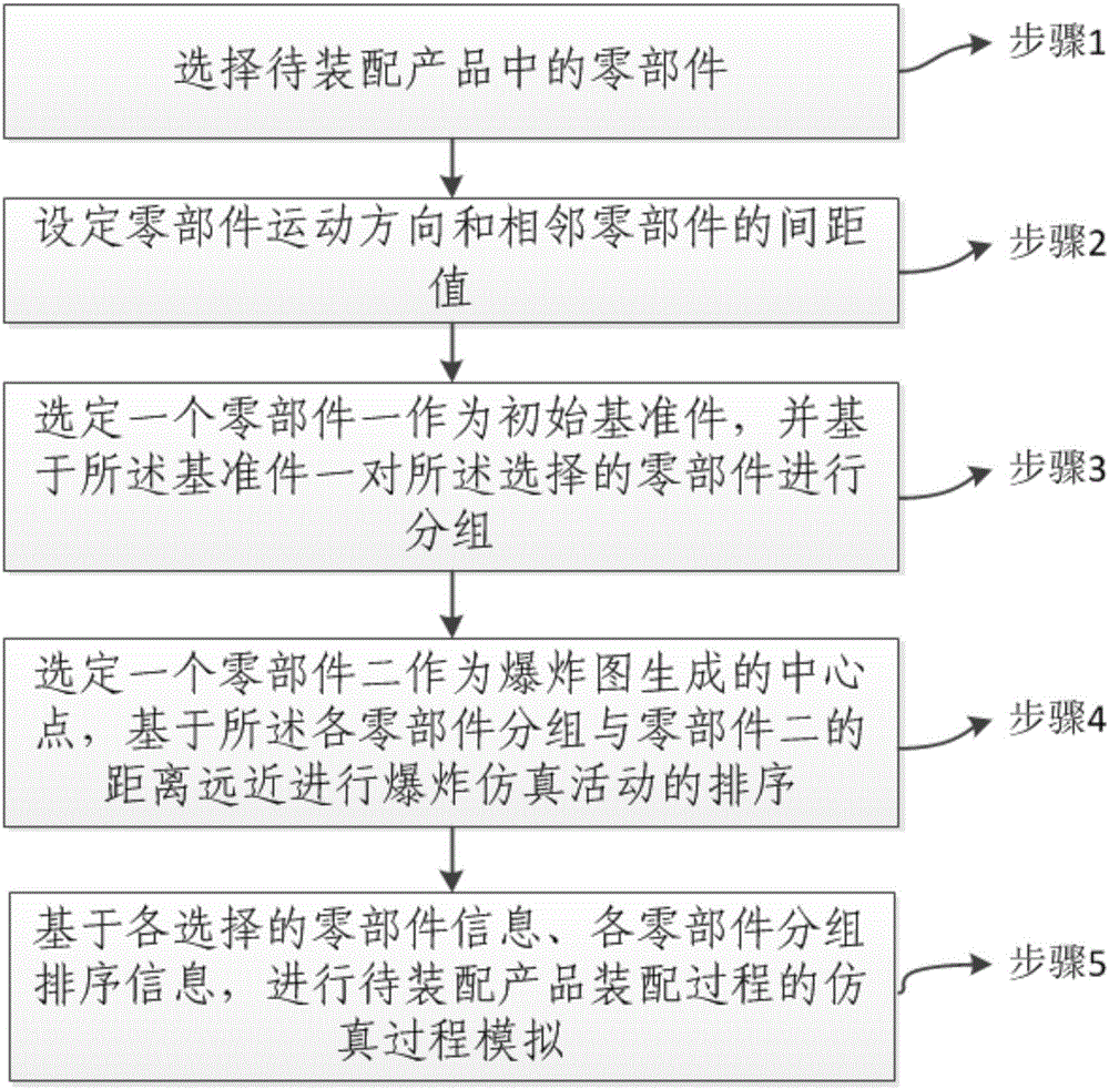
[0014] figure 1 In , a schematic flow chart of a method for generating an exploded view of an assembly process according to an embodiment of the present invention is given. Generally speaking, the method includes: step 1, select the components in the product to be assembled; step 2, set the movement direction of the components and the distance between adjacent components; step 3, select a component as the initial reference Parts, and group the selected parts based on the reference part; step 4, select a part two as the center point of the explosion diagram generation, based on the distance between the parts grouping and part two Sequencing of explosion simulation activit...


PUM


Abstract

The invention provides a method for generating an exploded view of the assembling process. The final view is generated by selecting parts, selecting the moving direction, grouping the parts and performing fine adjustment on the result. The problems that the operation of defining activities for each part separately is tedious and the operation of selecting the moving direction of the parts is prone to error in the traditional manual mode are avoided, and the operation of generating the exploded view can be greatly simplified.

Description

technical field [0001] The present invention relates to the technical field of computer-aided design, and more particularly, to a method for generating an exploded view of an assembly process. Background technique [0002] An exploded representation called an exploded view is often used for certain components in traditional assembly process documentation. In 3D assembly, a similar method can be used to show the decomposition effect of components. [0003] In the existing 3D assembly simulation system, in order to generate a view of the decomposition effect, it is necessary to analyze the relative position of each component, determine the movement direction and movement distance of the component, and define the simulation activity for each component separately. [0004] There are a lot of repetitions in the existing operations, the process of defining activities is relatively cumbersome, and it is difficult to adjust the movement direction of each part to be consistent, and ...

Claims


Application Information

Patent Timeline
Patent Type & Authority Applications(China)
IPC IPC(8): G06F17/50
CPCG06F30/20
Inventor 陈冠宏段梅常青
Owner WUHAN KAIMU INFORMATION TECH
Why Eureka
Try Eureka