
Display panel and device

A technology of display panel and display area, used in static indicators, instruments, electrical digital data processing, etc., and can solve problems such as uneven signal transmission

Inactive Publication Date: 2017-05-31
XIAMEN TIANMA MICRO ELECTRONICS
View PDF5 Cites 17 Cited by
  • Summary
  • Abstract
  • Description
  • Claims
  • Application Information

AI Technical Summary

Problems solved by technology

[0006] Embodiments of the present invention provide a display panel and a display device to solve the problem of uneven signal transmission in the display panel existing in the prior art

Method used


Image

  • Display panel and device
  • Display panel and device
  • Display panel and device

Examples


Embodiment Construction

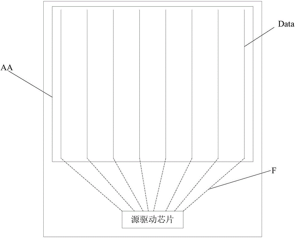
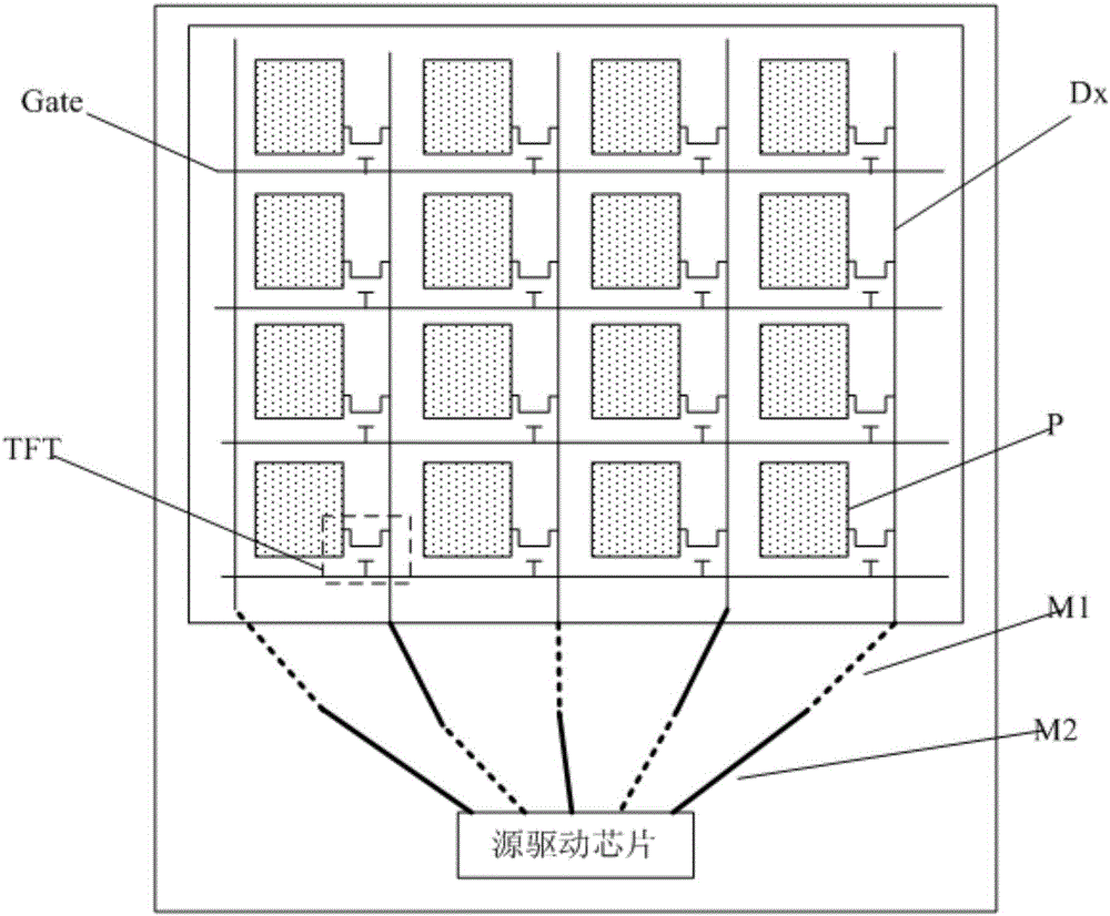
[0028] The specific implementation manners of the display panel and the display device provided by the embodiments of the present invention will be described in detail below with reference to the accompanying drawings.

[0029] An embodiment of the present invention provides a display panel, which may include: a plurality of signal lines located in the display area, and a driver chip located in the peripheral area of ​​one end of the signal lines; each output terminal of the driver chip is connected to each signal line through a lead wire in a one-to-one correspondence ; Each lead includes two metal segments arranged in different layers, and the line width of the first metal segment located in the first lead layer is greater than the line width of the second metal segment located in the second lead layer; wherein, the first lead layer adopts The resistivity of the metal is greater than the resistivity of the metal used in the second wiring layer.

[0030] The above-mentioned d...


PUM


Abstract

The invention discloses a display panel and device. The display panel comprises a plurality of signal lines in a display area and a driver chip which is located in a peripheral area at one ends of the signal lines. The output ends of the driver chip are correspondingly connected with the signal lines through leads one to one. Each lead comprises two metal segments arranged in different layers, and the line width of the first metal segment is larger than that of the second metal segment. In this way, each lead between the driver chip and the corresponding signal line is set as the two metal segments arranged in different layers, that is the driver chip is connected with the signal lines through double-layer lines, so that the display panel can be provided with a narrow bezel. Besides, when the line width of the first metal segment is larger than that of the second metal segment, teh impedance difference between the double-layer lines can be reduced, and the display effect of the display panel is improved.

Description

technical field [0001] The present invention relates to the field of display technology, in particular to a display panel and a display device. Background technique [0002] As we all know, flat-panel displays have many advantages that other displays cannot match, such as low power consumption, small size, light weight, and ultra-thin screen. The display panel used to realize the display function requires the control of the driver chip to realize the functions of progressive scanning and frame-by-frame refresh, so that the image data input to the display panel can be refreshed in real time, thereby realizing dynamic display. [0003] In the prior art, in order to realize the normal display of the display panel, the driving chip provides driving signals to the signal lines corresponding to the display area through the lead wires in the peripheral area, for example, the gate driver chip and the source driver chip respectively communicate with the gate lines of the display area...

Claims


Application Information

Patent Timeline
Patent Type & Authority Applications(China)
IPC IPC(8): G09G3/20G06F3/041
CPCG06F3/0412G09G3/2096
Inventor 唐艳芳刘冰萍周秀峰
Owner XIAMEN TIANMA MICRO ELECTRONICS
Learn More