Production equipment for cylindrical windings of substation transformers

A kind of production equipment, cylindrical technology, applied in the direction of inductance/transformer/magnet manufacturing, circuit, electrical components, etc., can solve the problems of uneven winding compactness, low transformer quality, low work efficiency, etc., and achieve horizontal Good beating effect, stable repeated beating force, and high qualified rate of transformers

Inactive Publication Date: 2018-05-18
李东志
View PDF3 Cites 0 Cited by
  • Summary
  • Abstract
  • Description
  • Claims
  • Application Information

AI Technical Summary

Problems solved by technology

[0003] In order to solve the above problems, the present invention provides a transformer substation cylindrical winding production equipment, which can solve the existing manual winding process of cylindrical windings and the need for artificial horizontal and vertical windings in transformers prepared by manually winding cylindrical windings Tapping winding compactness, inconsistent tapping speed, uneven tapping force, uneven winding compactness, poor winding performance, low work efficiency, non-uniform transformer performance, low transformer qualification rate and low transformer quality, etc. , can not only realize the automatic beating winding function of cylindrical windings, but also can prepare high-performance transformers containing cylindrical windings, without manual operation, with automatic beating winding compactness, uniform beating speed, uniform beating force, The winding tightness is uniform, the winding performance is good, the work efficiency is high, the performance of the transformer is uniform, the qualified rate of the transformer is high, and the quality of the transformer is good, etc.

Method used


Image

  • Production equipment for cylindrical windings of substation transformers
  • Production equipment for cylindrical windings of substation transformers
  • Production equipment for cylindrical windings of substation transformers

Examples


Embodiment Construction

[0027] In order to make the technical means, creative features, goals and effects achieved by the present invention easy to understand, the present invention will be further described below in conjunction with specific illustrations.

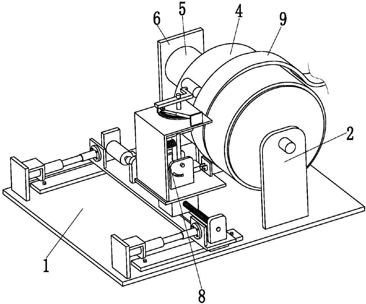
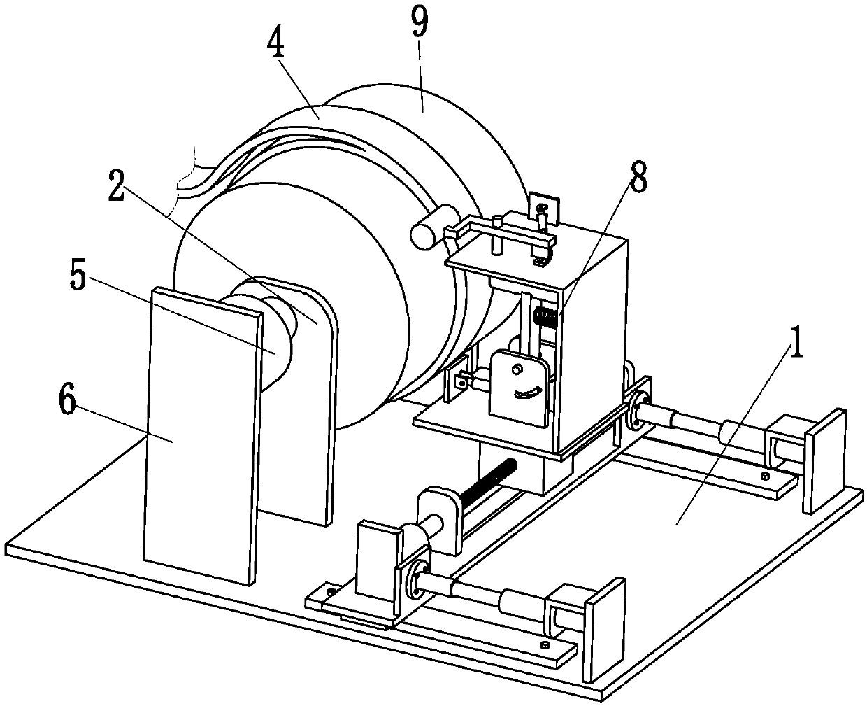
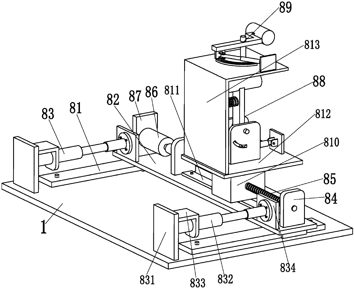
[0028] Such as Figure 1 to Figure 5 As shown, the embodiment of the present invention provides a transformer substation cylindrical winding production equipment, including a bottom plate 1, two mounting ears 2 are symmetrically installed on the upper end surface of the bottom plate 1, and the two mounting ears 2 are installed through bearings. There is an insulating cylinder 4, and the front end of the insulating cylinder 4 is equipped with a winding motor 5 through a coupling, and the bottom end of the winding motor 5 is installed on the vertical plate 6 through the motor base, and the vertical plate 6 is welded on the bottom plate 1. The motor 5 drives the insulating cylinder 4 to rotate on the two mounting ears 2. An auxiliary tightening dev...


PUM


Abstract

The invention relates to substation transformer bobbin winding production equipment and a transformer produced thereby; the substation transformer bobbin winding production equipment comprises a bottom plate, two mounting lugs are mounted symmetrically on the upper surface of the bottom plate, an insulating barrel is mounted between the two mounting lugs through a bearing, a winding motor is mounted at the front end of the insulating barrel through a coupling, the bottom end of the winding motor is mounted on a vertical plate through a motor seat, the vertical plate is welded to the bottom plate, the winding motor drives the insulating barrel to rotate on the two mounting lugs, an auxiliary knocking device is mounted at the right end of the bottom plate, a wire rod is wound to the outer wall of the insulating barrel, the wire rod wound to the right end of the insulating barrel is abutted to the auxiliary tightening device, the wire rod is wound to the outer wall of the insulating barrel several times to form a bobbing winding, and the auxiliary knocking device beats the wire rod transversely and longitudinally in automatic constant-speed manner during winding of the wire rod. The substation transformer bobbin winding production equipment provides full-automatic knocking winding for a bobbin winding, and can produce a high-performance transformer with the bobbin winding.

Description

technical field [0001] The invention relates to the technical field of transformer processing, in particular to a production equipment for cylindrical windings of substation transformers. Background technique [0002] The transformer uses the principle of electromagnetic induction to change the AC voltage. It is composed of a coil and a magnetic core. It has functions such as voltage conversion, current conversion, impedance conversion, isolation, and voltage stabilization. Therefore, it is widely used in substations. The main structure of the performance, in the production process of the transformer coil, to ensure that the outer diameter and axial height of the coil to be wound meet the design requirements, the winding must be wound tightly during the winding process to improve the winding precision. The degree of tightness, so that the winding is not damaged or the degree of damage is minimized in the case of a sudden short circuit, otherwise the outer diameter and axial ...

Claims


Application Information

Patent Timeline
Patent Type & Authority Patents(China)
IPC IPC(8): H01F41/071H01F41/094
CPCH01F41/071H01F41/094
Inventor 李东志
Owner 李东志
Why Eureka
Try Eureka