Multi-lobe high-gain UV (ultraviolet) omnidirectional AM (amplitude modulation) antenna

A high-gain, antenna technology, applied to antennas, devices that enable antennas to work in different bands at the same time, and structural forms of radiation elements, can solve problems such as unstable antenna performance, low receiving efficiency, and narrowing of the receiving frequency band, and achieve good results. Gain, more stable received signal, stronger received signal

Active Publication Date: 2017-05-31
GUANGDONG ZHONGYUAN CREATIVE TECH CO LTD
View PDF5 Cites 0 Cited by
  • Summary
  • Abstract
  • Description
  • Claims
  • Application Information

AI Technical Summary

Problems solved by technology

[0002] In the field of existing antennas, antennas can be divided into omnidirectional antennas and directional antennas according to the receiving direction, and among the antennas with omnidirectional functions, most of them cannot receive AM, FM or both AM and FM frequency band signals; and In the omnidirectional antenna that can receive AM or FM, a single flower wire is usually used to make a monopole dipole antenna, but this method is likely to cause problems such as narrowing of the receiving frequency band and low receiving efficiency, and the performance of the antenna itself is not good. stable, susceptible to disturbance

Method used


Image

  • Multi-lobe high-gain UV (ultraviolet) omnidirectional AM (amplitude modulation) antenna
  • Multi-lobe high-gain UV (ultraviolet) omnidirectional AM (amplitude modulation) antenna
  • Multi-lobe high-gain UV (ultraviolet) omnidirectional AM (amplitude modulation) antenna

Examples


Embodiment Construction

[0018] The present invention will be further described below in conjunction with specific embodiment:

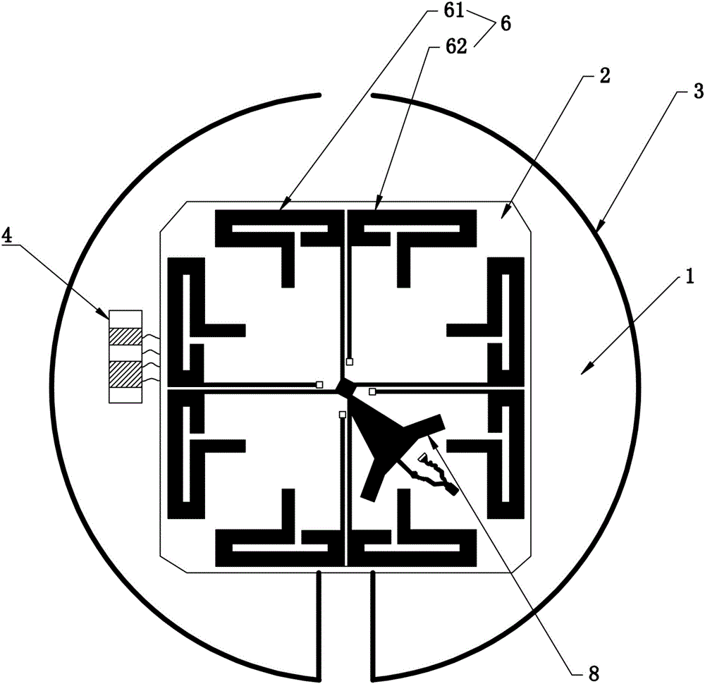
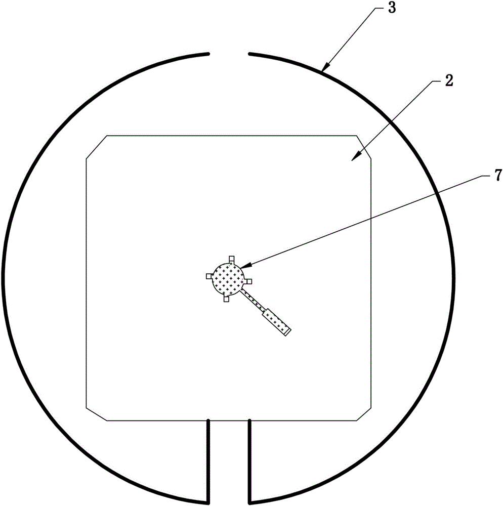
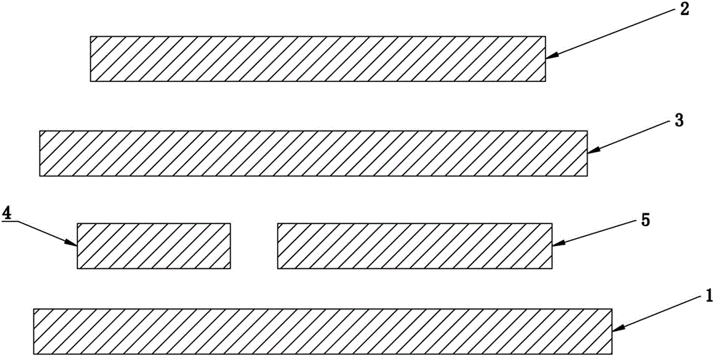
[0019] See attached figure 1 to attach image 3 , a multi-lobe high-gain UV omnidirectional band AM antenna, including an insulating plate 1, a substrate 2 arranged above the insulating plate 1, two V-frequency signal radiation units 3 located between the insulating plate 1 and the substrate 2, and an AM vibrator winding The wire magnetic bar 4, the amplifying circuit 5, and the four sets of signal radiation parts 6 printed on the substrate 2, the feed unit 7 and the impedance matching unit 8; among them, two V frequency signal radiation units 3 are distributed around the insulating board 1 for the whole To receive VHF frequency band signals, the two V-frequency signal radiation units 3 are respectively connected to the amplifier circuit 5 for outputting signals to the amplifier circuit 5, and the two V-frequency signal radiation units 3 are two dipole vibrator floral wires...


PUM


Abstract

The invention discloses a multi-lobe high-gain UV (ultraviolet) omnidirectional AM (amplitude modulation) antenna which comprises an insulating plate, a substrate, two V frequency signal radiation units, an AM vibrator winding magnetic rod and an amplifying circuit. The substrate is arranged above the insulating plate, the two V frequency signal radiation units are positioned between the insulating plate and the substrate, four signal radiation portions, a feeder unit and an impedance matching unit are printed on the substrate, the four signal radiation portions are annularly arrayed on the upper surface of the substrate, so that the antenna receives UHF (ultra-high frequency) band signals in a 360-degree direction, the two V frequency signal radiation units are distributed around an insulating layer and used for receiving VHF (very high frequency) band signals, and the AM vibrator winding magnetic rod is arranged on the insulating layer and used for receiving AM and FM (frequency modulation) signals. By the aid of the radiation units for receiving UHF and VHF and the winding magnetic rod for receiving AM and FM, the antenna can receive the UHF, VHF, AM and FM band signals more strongly and stably, signal structure frequency bands are widened, the VHF frequency band receives the signals in an omnidirectional manner through a circular structure, and the UHF frequency band receives the signals in an omnidirectional manner through the four radiation portions.

Description

technical field [0001] The invention relates to the technical field of printed antennas, in particular to a multi-lobe high-gain UV omnidirectional band AM antenna. Background technique [0002] In the field of existing antennas, antennas can be divided into omnidirectional antennas and directional antennas according to the receiving direction, and among the antennas with omnidirectional functions, most of them cannot receive AM, FM or both AM and FM frequency band signals; and In the omnidirectional antenna that can receive AM or FM, a single flower wire is usually used to make a monopole dipole antenna, but this method is likely to cause problems such as narrowing of the receiving frequency band and low receiving efficiency, and the performance of the antenna itself is not good. Stable and easily disturbed. Contents of the invention [0003] Aiming at the deficiencies of the prior art, the object of the present invention is a multi-lobe high-gain UV omnidirectional ante...

Claims


Application Information

Patent Timeline
IPC IPC(8): H01Q1/36H01Q1/38H01Q5/20
CPCH01Q1/36H01Q1/38H01Q5/20
Inventor 张伟强
Owner GUANGDONG ZHONGYUAN CREATIVE TECH CO LTD
Why Eureka
Try Eureka