
Group unmanned aerial vehicle power supply device

A technology for power supply devices and unmanned aerial vehicles, which is applied in the direction of circuit devices, battery circuit devices, current collectors, etc., can solve problems such as difficulty in implementation, manpower input, reliability, lack of flexibility and convenience, and achieve broad application prospects. The effect of solid docking

Active Publication Date: 2017-05-31
河北省自动化研究所有限公司
View PDF9 Cites 10 Cited by
  • Summary
  • Abstract
  • Description
  • Claims
  • Application Information

AI Technical Summary

Problems solved by technology

For the former, since the relatively mature battery technology has developed to the bottleneck period, a larger battery capacity means a larger battery volume and weight, so increasing the battery capacity will definitely affect the maneuverability and lightweight of the UAV; For the method of power supply through multiple times, if it is based on the charging technology of the traditional contact power conduction method, it means that the UAV needs to return to the base station or home port when it needs to replenish power, and invest in manpower. Its charging, obviously, this method is insufficient in terms of reliability, flexibility, convenience, etc., and the hovering charging form based on this method is low in safety, and has high requirements on the technical performance of the drone , it is difficult to realize

Method used


Image

  • Group unmanned aerial vehicle power supply device
  • Group unmanned aerial vehicle power supply device
  • Group unmanned aerial vehicle power supply device

Examples


Embodiment Construction

[0021] The following will clearly and completely describe the technical solutions in the embodiments of the present invention with reference to the accompanying drawings in the embodiments of the present invention. Obviously, the described embodiments are only some, not all, embodiments of the present invention. Based on the embodiments of the present invention, all other embodiments obtained by persons of ordinary skill in the art without making creative efforts belong to the protection scope of the present invention.

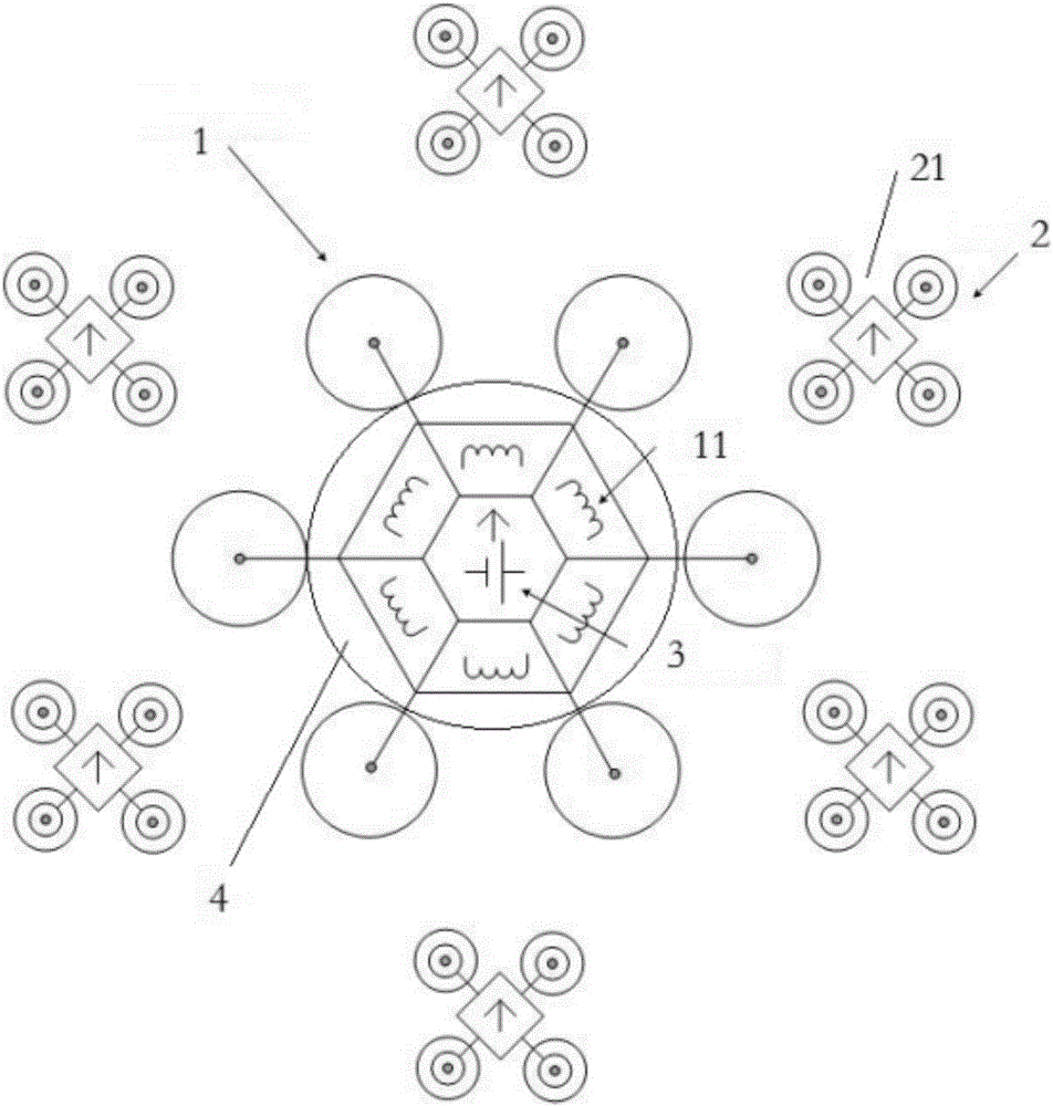
[0022] Now refer to Figure 1-4 An embodiment of the swarm unmanned aerial vehicle power supply device of the present invention is described in detail. in, figure 1 A brief schematic diagram of a power supply device for swarm drones according to an embodiment of the present invention is shown. Such as figure 1 As shown, the group UAV power supply device includes a host 1 and six UAVs 2 . Preferably, the host 1 is a medium-to-large six-rotor UAV, which uses...


PUM


Abstract

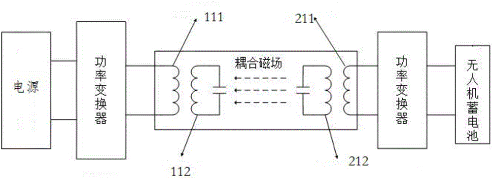
The invention discloses a group unmanned aerial vehicle power supply device of no-contact charging based on electromagnetic coupling. The group unmanned aerial vehicle power supply device comprises a main vehicle and at least one unmanned aerial vehicle, wherein fuel is provided for the main vehicle by fuel oil, the main vehicle carries at least one power source and comprises multiple transmitting terminals, each transmitting terminal is provided with a transmitting coil and a first resonance coil corresponding to the transmitting coil, and the power source is electrically connected to the transmitting terminal; each unmanned aerial vehicle carries a rechargeable device and comprises a receiving terminal, the receiving terminal is provided with a receiving coil and a second resonance coil corresponding to the receiving coil, the receiving terminal is electrically connected to the rechargeable device, wherein each transmitting terminal can charge one unmanned aerial vehicle, the transmitting coils, the first resonance coils, the second resonance coil and the receiving coil constitute an electromagnetic resonance type coupling mechanism, meanwhile the main vehicle further comprises a landing platform, and the landing platform is connected to a base of the main vehicle in an attached mode and is used for supporting the unmanned aerial vehicle.

Description

technical field [0001] The present invention relates to a power supply system for unmanned aerial vehicles, in particular to a group unmanned aerial vehicle power supply device based on electromagnetic coupling non-contact charging, which is used to charge multiple small unmanned aerial vehicles at the same time to ensure the battery life of unmanned aerial vehicles . Background technique [0002] Compared with manned aircraft, UAVs have many advantages: small and light, not easy to be found, low development and maintenance costs, good maneuverability, and low take-off and landing requirements. With the popularization of drones, its application fields have covered scientific research, civilian and military. There are more than 30 countries engaged in the research and production of UAVs in the world, and the number of basic types of UAVs has increased to more than 300. [0003] Among the various indicators for evaluating the performance of drones, the endurance of drones is...

Claims


Application Information

Patent Timeline
Patent Type & Authority Applications(China)
IPC IPC(8): H02J7/00H02J50/12
CPCH02J5/005H02J7/025
Inventor 张立国商建超李玉霞刘瑞波申莉竹姬少英崔利洋张百超
Owner 河北省自动化研究所有限公司
Learn More