
Magnetic field enhanced consequent-pole permanent magnet motor

A permanent magnet motor, alternating pole technology, applied in the direction of magnetic circuit rotating parts, magnetic circuit shape/style/structure, etc., can solve problems such as high price, reduced output torque capacity, surface-mounted permanent magnets falling off, etc. The effect of reducing production cost and quantity

Active Publication Date: 2017-05-31
NANJING UNIV OF AERONAUTICS & ASTRONAUTICS
View PDF5 Cites 7 Cited by
  • Summary
  • Abstract
  • Description
  • Claims
  • Application Information

AI Technical Summary

Problems solved by technology

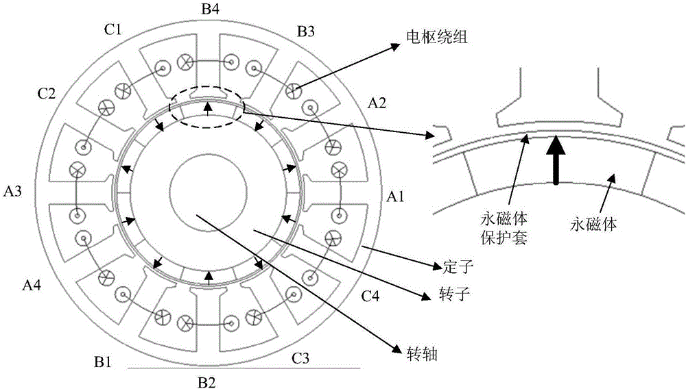
The surface of the rotor is completely covered by permanent magnets, and the materials used for the permanent magnets are expensive rare earth permanent magnet materials, so the production cost of surface-mounted permanent magnet motors is relatively high
[0004] In addition, the centrifugal force of the rotor may cause the surface-mounted permanent magnet to fall off. In order to avoid irreparable damage, it is necessary to add a non-magnetic protective cover outside the permanent magnet, which not only increases the cost, but also makes the equivalent between the stator and rotor Larger air gap reduces output torque capability

Method used


Image

  • Magnetic field enhanced consequent-pole permanent magnet motor
  • Magnetic field enhanced consequent-pole permanent magnet motor
  • Magnetic field enhanced consequent-pole permanent magnet motor

Examples


Embodiment Construction

[0023] The technical solutions of the present invention will be described in detail below in conjunction with the accompanying drawings.

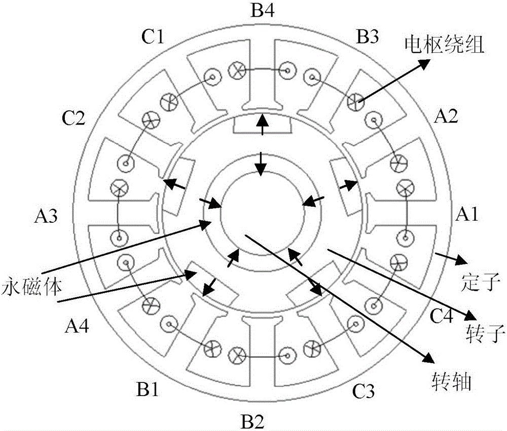
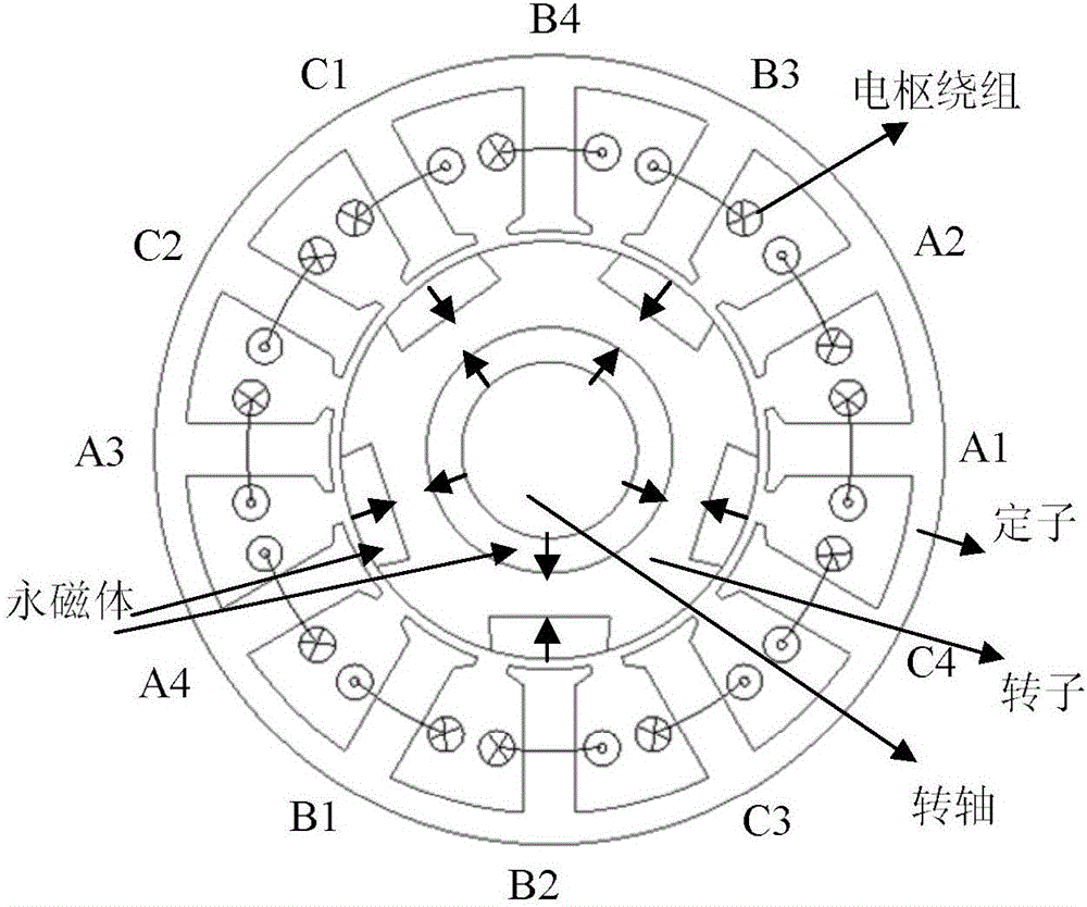
[0024] The present invention takes a three-phase 12 / 10-pole permanent magnet motor as an example, and adopts two-stage rotors. A, B, and C three-phase windings are used, and the A-phase armature winding is composed of A1, A2, A3, and A4 coils in series, and the B-phase and C-phase armature windings are analogized in turn. The motor consists of 12 stator poles.

[0025] The magnetic field-enhanced alternating pole permanent magnet motor includes two rotors, the two rotors are sequentially connected along the rotor axis, and there are axially magnetized annular permanent magnets between the adjacent two rotors, and the adjacent annular permanent magnets The direction of magnetization is opposite. The structure of the two rotors is the same, such as Figure 2(a) , 2(b) As shown, five salient poles are uniformly arranged on the surface of e...


PUM


Abstract

The invention discloses a magnetic field enhanced consequent-pole permanent magnet motor, comprising n rotor sections, wherein the n rotor sections are connected in sequence in the axial direction of a rotor, an annular permanent magnet magnetized axially is arranged between two adjacent rotor sections, and the magnetized directions of the adjacent annular permanent magnets are opposite; the n rotor sections are of the same structure, a plurality of salient poles are uniformly arranged on the surface of each rotor section, a permanent magnet is embedded into a groove between the adjacent salient poles, and an alternate arrangement structure of the salient poles and the permanent magnets is formed on the surface of the rotor; the magnetized directions of the permanent magnets on the surface of the same rotor section are same, and the magnetized directions of the permanent magnets on the surfaces of the adjacent rotor sections are opposite; a hollow cylindrical permanent magnet is arranged between the inner side of each rotor section and a rotating shaft, and the magnetized directions of the permanent magnets on the inner sides of the two adjacent rotor sections are opposite. The magnetic field enhanced consequent-pole permanent magnet motor overcomes the defects of a traditional surface-mounted permanent magnet motor, reduces the cost of a permanent magnet material, and enhances the output torque.

Description

technical field [0001] The invention belongs to the technical field of motor structure, and in particular relates to a magnetic field enhanced alternating pole permanent magnet motor. Background technique [0002] In recent years, due to its high torque density and high efficiency, permanent magnet motors have been widely used in home appliances, electric vehicles, wind power generation, aerospace and other occasions. [0003] The traditional surface-mounted permanent magnet motor has a structure such as figure 1 shown. The surface of the rotor is completely covered by permanent magnets, and the materials used for the permanent magnets are expensive rare earth permanent magnet materials, so the production cost of the surface-mounted permanent magnet motor is relatively high. [0004] In addition, the centrifugal force of the rotor may cause the surface-mounted permanent magnet to fall off. In order to avoid irreparable damage, it is necessary to add a non-magnetic protecti...

Claims


Application Information

Patent Timeline
IPC IPC(8): H02K1/27H02K1/24
CPCH02K1/24H02K1/27H02K1/2746
Inventor 王凯李健吴科明刘闯
Owner NANJING UNIV OF AERONAUTICS & ASTRONAUTICS
Learn More