
Feeding and blanking mechanism of rotor winding machine

A winding machine and rotor technology, applied in the field of machinery, can solve the problems of high manufacturing cost, high failure rate, and low efficiency of mechanical arms, and achieve the effects of fast working speed, accurate loading and unloading, and high efficiency

Pending Publication Date: 2017-05-31
浙江巨力电机成套设备有限公司
View PDF7 Cites 9 Cited by
  • Summary
  • Abstract
  • Description
  • Claims
  • Application Information

AI Technical Summary

Problems solved by technology

[0003] The winding machine is further divided into a fully automatic winding machine connected to the assembly line and a single winding machine. Large-scale factories generally use assembly line operations. Their winding machines generally complete the loading and unloading of the rotor through the mechanical arm. Unloading can realize automatic operation, while the single-body winding machine generally manually pushes the rotor into the winding machine to realize winding processing. The operation is cumbersome and the efficiency is not high. The unqualified rate is also relatively high; and in order to solve the above problems, many rotor winding machines use mechanical arms to directly load and unload the rotor, but the manufacturing cost of the mechanical arm is high, and the efficiency also has a lot of room for improvement.

Method used


Image

  • Feeding and blanking mechanism of rotor winding machine
  • Feeding and blanking mechanism of rotor winding machine
  • Feeding and blanking mechanism of rotor winding machine

Examples


Embodiment Construction

[0019] The following are specific embodiments of the present invention and in conjunction with the accompanying drawings, the technical solutions of the present invention are further described, but the present invention is not limited to these embodiments.

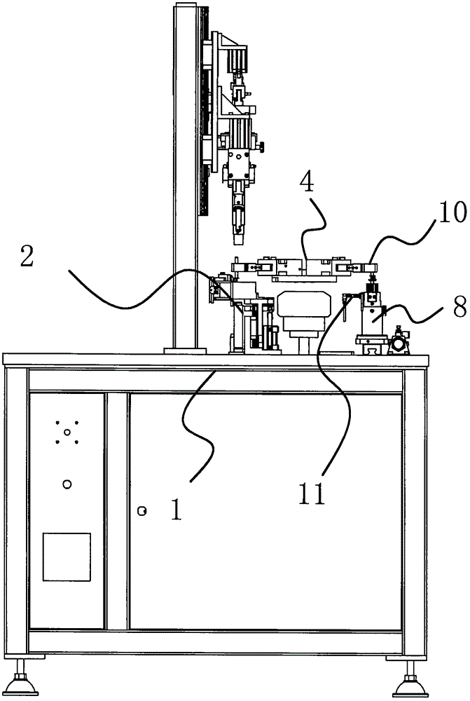
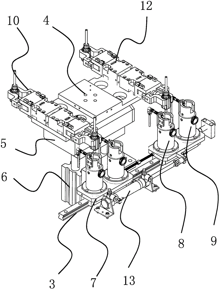
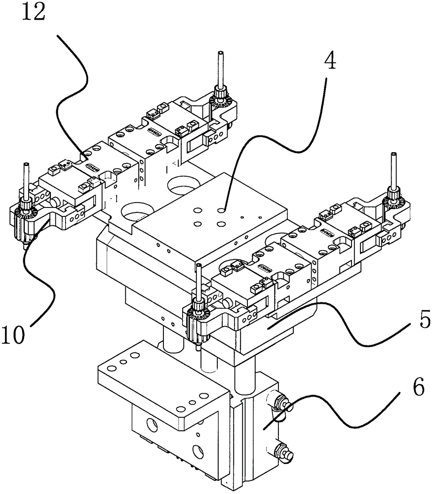
[0020] Such as Figure 1-3 The loading and unloading mechanism of a rotor winding machine is shown. The loading and unloading mechanism includes a frame 1, and the frame 1 is provided with a clamping part 2, a linear slide rail 3, a rotating plate 4, a driving part 5 and a driving part 2 6. The linear slide rail 3 is provided with a slider 7 that can slide on the branch line slide rail. The slider 7 is provided with a feeding rotor seat 8 and a feeding rotor seat 9. The driving part 2 6 is fixed on the frame 1. The driver one 5 is arranged on the driver two 6 top and the driver two 6 can drive the driver one 5 to move up and down in the vertical direction, the rotary plate 4 is arranged on the driver one 5 and the driver o...


PUM


Abstract

The invention discloses a feeding and blanking mechanism of rotor winding machine which belongs to a technical field of machine. The feeding and blanking mechanism of rotor winding machine has the advantages of solving the technical problems of higher risks and low efficiency of manual feeding and blanking of existing feeding and blanking mechanism. The feeding and blanking mechanism comprises a rack provided with a clamping part, straight sliding rail, a rotor plate, an actuator one and an actuator two. The straight sliding rail is provided with a sliding block capable of sliding in the straight sliding rail. The sliding block is provided with a feeding rotor housing and a blanking housing. The actuator two is fixedly disposed on the rack. The actuator one is disposed above the actuator two and the actuator two is capable of driving the actuator one slide up and down along the vertical direction. The rotor plate is disposed on the actuator one and the actuator one is capable of driving the rotor plate move in horizontal direction. The rotor plate is provided with paws. The paws are disposed above the feeding rotor housing and the clamping part respectively in the front and back of the rotor plate. The feeding and blanking mechanism of rotor winding machine has the advantages of having high operating speed, high efficiency,a fixed rotation angle, accurate feeding and blanking and high stability.

Description

technical field [0001] The invention belongs to the technical field of machinery, and relates to a loading and unloading mechanism of a rotor winding machine. Background technique [0002] The rotor of the motor generally includes the rotor core and the rotor winding. Many manufacturers use high-speed stamping machine tools to process and produce the rotor core, and then wind the copper wire on the rotor core through special equipment to form the rotor winding. The quality is inseparable from the processing quality of the rotor core and the winding quality of the rotor winding. The rotor windings on the market are generally processed by winding machines. [0003] The winding machine is further divided into a fully automatic winding machine connected to the assembly line and a single winding machine. Large-scale factories generally use assembly line operations. Their winding machines generally complete the loading and unloading of the rotor through the mechanical arm. Unload...

Claims


Application Information

Patent Timeline
IPC IPC(8): H02K15/08
CPCH02K15/08
Inventor 章宏亮
Owner 浙江巨力电机成套设备有限公司
Learn More