Check patentability & draft patents in minutes with Patsnap Eureka AI!

Moving target tracking method

A technology of moving targets and motion parameters, applied in the field of computer vision, can solve problems such as large amount of calculation, and achieve the effect of simplifying the process of calculation, reducing complexity and low implementation cost

Inactive Publication Date: 2017-05-31
UHDEVICE ELECTRONICS JIANGSU CO LTD
View PDF8 Cites 1 Cited by
  • Summary
  • Abstract
  • Description
  • Claims
  • Application Information

AI Technical Summary

Problems solved by technology

[0006] The purpose of the present invention is to provide a moving target tracking method to solve the problem in the prior art that the calculation amount is too large and the tracking of the moving target cannot be completed in a timely manner

Method used


Image

  • Moving target tracking method
  • Moving target tracking method
  • Moving target tracking method

Examples


Embodiment Construction

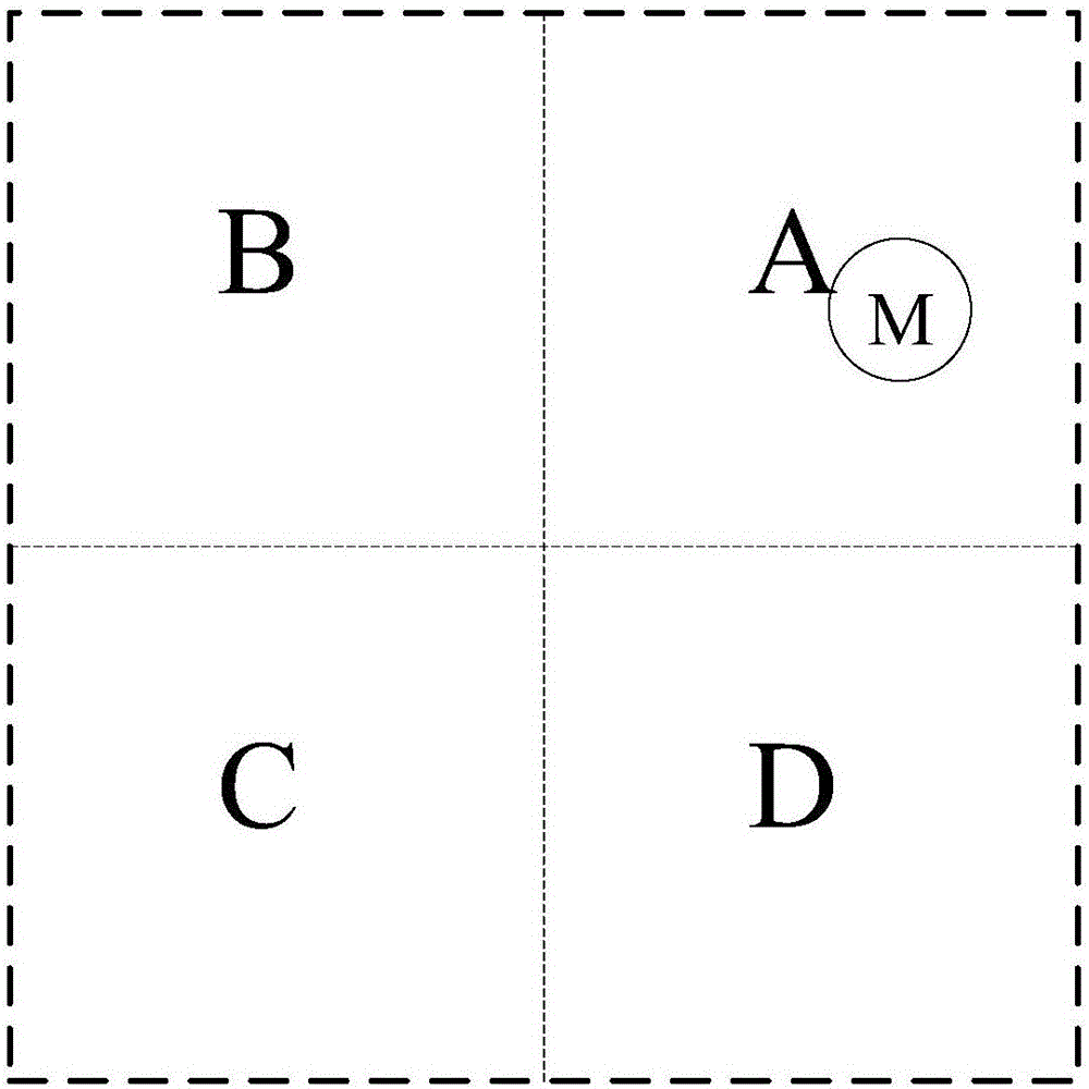
[0047] see Figure 1A and 1B As shown, it is a schematic diagram and a schematic flowchart of the first embodiment implementing the moving object tracking method of the present invention. Implementing the moving target tracking method of the present invention is to utilize a high-speed high-definition camera device to detect the motion parameters of the moving target relative to the high-speed high-definition camera device, the high-speed high-definition camera device is provided with an image sensor array, and the moving target tracking method comprises the following steps:

[0048] Step 1: The image sensor array of the high-speed high-definition camera device is divided into multiple sub-image sensor arrays, for example, the image sensor array of the high-speed high-definition camera device is a 48*48 array, then it can be divided into four 24*24 sub-arrays image sensor array, such as Figure 1A The four sub-image sensor arrays shown in A, B, C, and D;

[0049] Step 2: Util...


PUM


Abstract

The invention discloses a moving target tracking method. According to the moving target tracking method, a high-speed high-definition camera device monitor motion parameters of a moving target with respect to the high-speed high-definition camera device. The high-speed high-definition camera device is provided with an image sensor array. The moving target tracking method comprises the steps of dividing the image sensor array of the high-speed high-definition camera device into multiple sub-image sensor arrays; photographing a panoramic picture including the motion target by utilizing the high-speed high-definition camera device; determining a sub-image sensor array corresponding to the moving target; obtaining a local image photographed by the sub-image sensor array which corresponds to the moving target according to the time sequence; carrying out correlation arithmetic on the local image photographed by the sub-image sensor array and calculating the motion parameters of the moving target.

Description

[0001] 【Technical field】 [0002] The invention belongs to the field of computer vision, in particular to a moving target tracking method. [0003] 【Background technique】 [0004] The existing computer vision mainly studies the recognition of the target object, the positioning of the target object and the motion analysis of the target object. The existing technologies all use the entire image to perform correlation calculations to determine the displacement of the moving target. The disadvantage is that the amount of data calculation is too large to complete the real-time tracking of moving targets, which is inconvenient for subsequent management. [0005] 【Content of invention】 [0006] The object of the present invention is to provide a moving target tracking method to solve the problem in the prior art that the calculation amount is too large and the tracking of the moving target cannot be completed in a timely manner. [0007] In order to achieve the above object, impleme...

Claims


Application Information

Patent Timeline
Patent Type & Authority Applications(China)
IPC IPC(8): H04N5/225H04N7/18
CPCH04N7/18H04N23/45
Inventor 刘建
Owner UHDEVICE ELECTRONICS JIANGSU CO LTD
Features
  • R&D
  • Intellectual Property
  • Life Sciences
  • Materials
  • Tech Scout
  • Unparalleled Data Quality
  • Higher Quality Content
  • 60% Fewer Hallucinations
Learn More