

Radius end mill
A technology of end mills and arc heads, which is applied in the field of end mills with arc heads, can solve problems such as interference, damage to the strength of the bottom edge and peripheral edge, and reduction in wall thickness, and achieve the effect of preventing defects
Inactive Publication Date: 2017-05-31
MITSUBISHI MATERIALS CORP
View PDF7 Cites 4 Cited by
- Summary
- Abstract
- Description
- Claims
- Application Information
AI Technical Summary
Problems solved by technology
[0014] Therefore, there is a possibility that the wall thickness of the bottom edge adjacent in the direction of rotation of the end mill and the wall thickness of the front end of the end mill body connected to the outer peripheral edge on the opposite side of the direction of rotation of the end mill may be reduced.
As a result, the strength of the bottom cutting edge and the peripheral cutting edge may be impaired, or the center groove may be formed to the flank of the peripheral cutting edge adjacent in the direction of rotation of the end mill to cause interference.
Method used
View moreImage
Smart ImageViewing Examples

Examples
Embodiment
[0071] Next, examples of the present invention are given to verify the effects of the present invention.
[0072] In this example, according to the above-mentioned embodiment, the central groove depth angle θ (°) is set to be less than 50°, and the sum of the axial rake angle difference α (°) and the central groove depth angle θ (°) is manufactured. (θ(°)+α(°)) is set to be more than 60° for eight types of arc head end mills.
Login to View More PUM
 Abstract
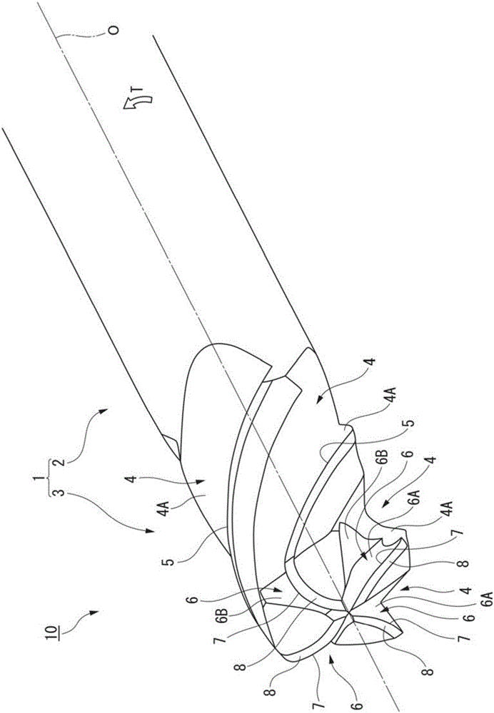
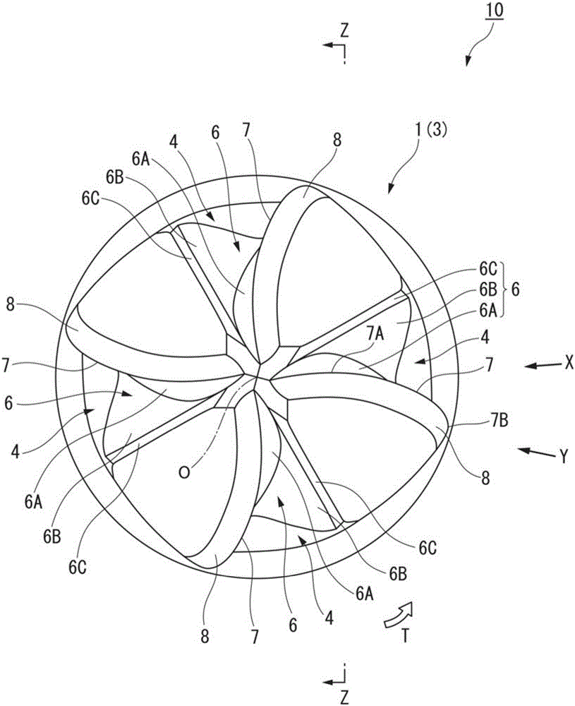
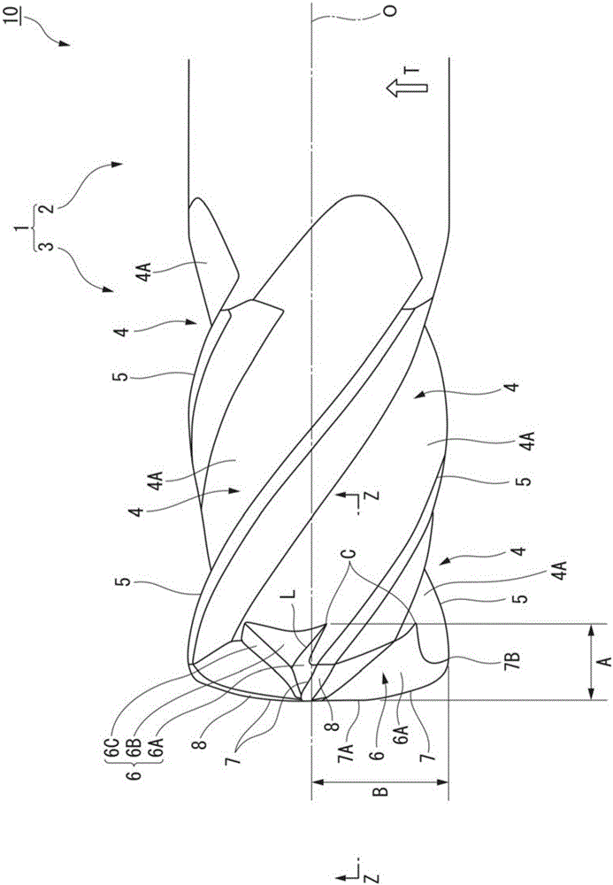
The present invention is a radius end mill (10) equipped with end cutting edges (7) formed so that the rotation tracks thereof around the axial line (O) trace a convex surface. The convex surface is formed so that in cross-sectional view along the axial line, the convex surface has a convex line such that the radius of curvature at the inner portion (7A), which is located closer to the axial line than the tip periphery (7B) of the end mill body (1), is larger than the radius of curvature at the tip periphery. The gash depth angle theta (degree) calculated from theta = tan-1 (A / B) based on the distance A (mm) from the tip (7A) of the end cutting edge to the rearmost edge of a gash (6) in the axial direction and the radius B (mm) from the axial line to the point of contact (7B) between the peripheral cutting edge (5) and the end cutting edge is set to be not more than 50 degrees. The sum (theta (degree) + alpha (degree)) of the gash depth angle alpha 2 (degree) and the axial direction rake angle difference alpha (degree) = (theta (degree) - alpha (degree)) between the axial direction rake angle alpha 2 (degree) of the end cutting edge at the point of contact and the axial direction rake angle alpha 1 (degree) of the end cutting edge at the tip is set to be at least 60 degrees.
Description
technical field [0001] The present invention relates to a circular arc head end mill. The arc head end mill is formed with a bottom edge at the front end of the end mill main body. The rotation track of the bottom edge around the axis of the end mill main body is described as a convex curved surface. And it extends toward the rear end side toward the outer peripheral side of the end mill main body, and contacts the front end of the outer peripheral cutting edge. [0002] Specifically, it relates to an arc whose radius of curvature of the convex curve formed by the above-mentioned convex curved surface described by the bottom edge on the section along the above-mentioned axis is set to be larger on the front end inner peripheral side of the end mill main body than on the front end outer peripheral side. head end mill. [0003] This application claims priority based on Patent Application No. 2014-206297 for which it applied in Japan on October 7, 2014, and uses the content here...
Claims
Login to View More Application Information
Patent Timeline
 Patent Type & AuthorityApplications(China)
IPC IPC(8): B23C5/10
CPCB23C5/10B23C2210/04B23C2210/0428B23C2210/045B23C2210/54
Inventor深田耕司
OwnerMITSUBISHI MATERIALS CORP