Pneumatic vehicle tyre

A technology for pneumatic tires and vehicles, applied in vehicle parts, tire parts, tire treads/tread patterns, etc., to achieve the effect of improving receiving capacity

Active Publication Date: 2017-05-31
CONTINENTAL REIFEN DEUTSCHLAND GMBH
View PDF7 Cites 2 Cited by
  • Summary
  • Abstract
  • Description
  • Claims
  • Application Information

AI Technical Summary

Problems solved by technology

However, the hitherto homogeneous distribution of these surface structures makes it possible to receive the water film uniformly only

Method used


Image

  • Pneumatic vehicle tyre
  • Pneumatic vehicle tyre
  • Pneumatic vehicle tyre

Examples


Embodiment Construction

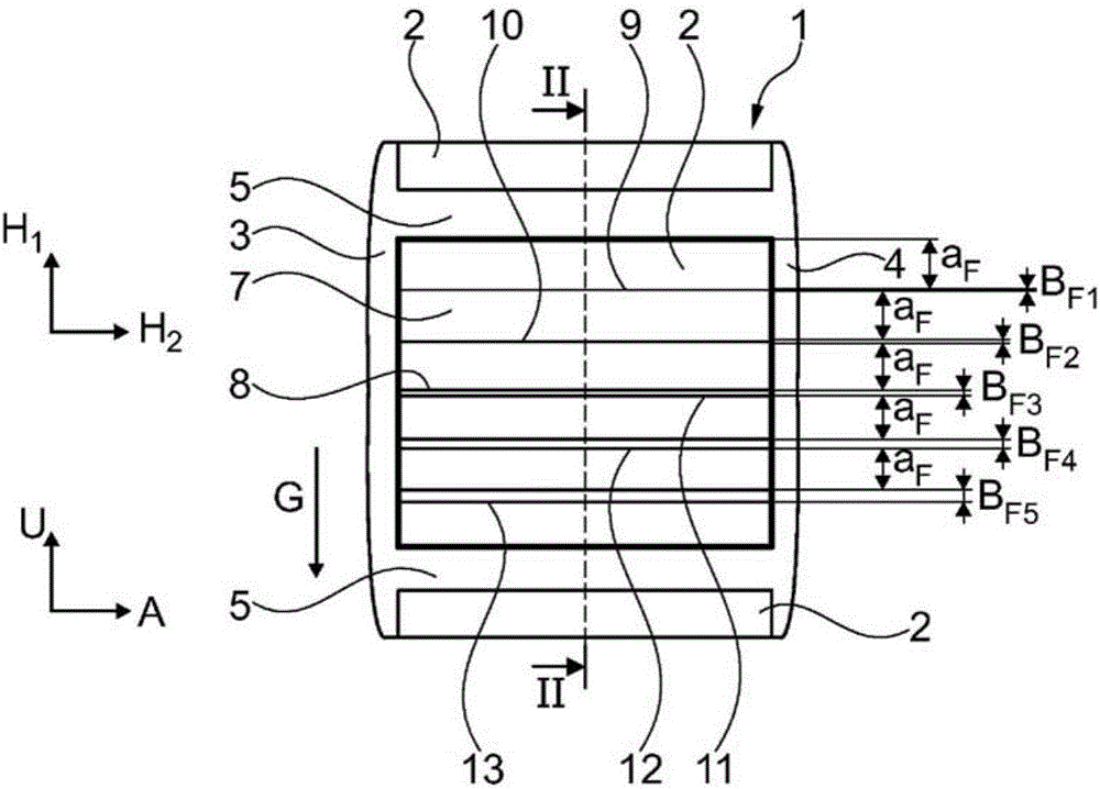
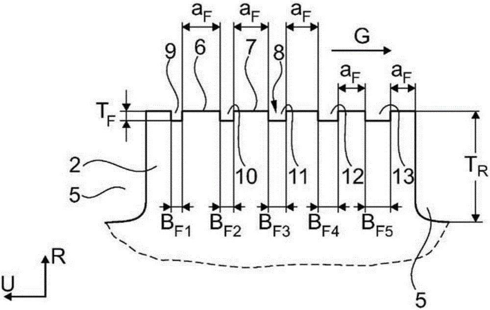
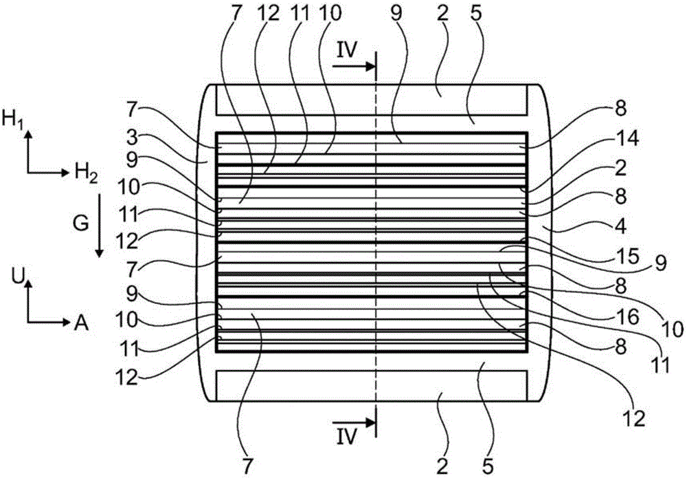
[0036] figure 1 and 2 A partial view showing a tread pattern of a vehicle pneumatic tire for a PKW (passenger car) with a known type of block row 1 formed at the circumference of the vehicle pneumatic tire Oriented in direction U and extending over the entire circumference of the vehicle pneumatic tire. The block row 1 is formed in a known manner from a plurality of radially raised block units 2 arranged one behind the other in the circumferential direction U of the pneumatic vehicle tire and correspondingly passed through a plurality of transverse The grooves 5 are spaced apart from each other. The row of blocks 1 is bounded in the axial direction A of the vehicle pneumatic tire towards one axial side by a circumferential groove 3 and towards the other axial side by a circumferential groove 4 in a known manner. These circumferential grooves 3 and 4 extend in a known manner over the entire circumference of the vehicle pneumatic tire and are oriented in the circumferential ...


PUM


Abstract

A tread profile of a pneumatic vehicle tyre having profile block elements (2) which are spaced apart from one another by profile grooves (3, 4, 5) and which are each bounded outwardly by a radially outer surface (6) which forms the ground contact face, wherein a plurality of additional fine grooves (9, 10, 11, 12), which extend along a second main direction of extent and are embodied with a groove width Bp and with a groove depth TF, are arranged one behind the other in a first main direction of extent in the radially outer surface (6) of the profile block elements (2), characterized in that the groove width Bp is 0.05 mm < BF < 0.4 mm and the groove depth TF where TF is < 0.05 mm, and in that at least the fine grooves (9, 10, 11, 12), arranged one behind the other within a surface section (7) of the radially outer surface (6) of a profile block element (2) are embodied with different groove widths Bp, wherein the groove width Bp of these fine grooves (9, 10, 11, 12), arranged one behind the other in the surface section (7), increases in a first orientation of the first main direction of extent, viewed along the extent of the surface section (7) in particular from the fine groove (9, 10, 11) to the fine groove (10, 11, 12).

Description

technical field [0001] The present invention relates to a tread pattern of a pneumatic tire for vehicles, the tread pattern having block units spaced apart from each other by a plurality of sipes, and the block units are respectively formed outwardly in the radial direction by a A radially outer surface limit forming the ground-contacting surface, wherein a plurality of additional sipes arranged one behind the other along a first main direction of extension are arranged in the radially outer surface of at least some of the block elements, the sipe The groove extends along a second main direction of extension and is formed with a groove width B F and has a groove depth T F . Background technique [0002] Such tread patterns are known. It is known to form a tread pattern with a plurality of block units delimited by a plurality of sipe. The grooves are formed with a groove width of more than two millimeters and with a groove depth of several millimeters. The sipe formed in...

Claims


Application Information

Patent Timeline
Patent Type & Authority Applications(China)
IPC IPC(8): B60C11/12
CPCB60C11/1236B60C2011/1209B60C2011/1231B60C2011/1286
Inventor 克劳斯·维泽马蒂亚斯·森
Owner CONTINENTAL REIFEN DEUTSCHLAND GMBH
Why Eureka
Try Eureka