Lifter with electropermanent magnets

A technology of lifters and permanent magnets, which is applied in the direction of cranes, permanent magnets, load suspension components, etc., can solve problems such as dangerous temperature and shorten the operation time of lifters, and achieve the effect of ensuring operability

Inactive Publication Date: 2017-05-31
SGM MAGNETICS SPA
View PDF9 Cites 1 Cited by
  • Summary
  • Abstract
  • Description
  • Claims
  • Application Information

AI Technical Summary

Problems solved by technology

As mentioned above, this heat transfer greatly reduces the operating time of the jack, as this leads to hazards in its critical components (i.e., the stationary magnet, the reversible magnet, and the commutating coil in chronological order) within a relatively short period of time. temperature

Method used


Image

  • Lifter with electropermanent magnets
  • Lifter with electropermanent magnets

Examples


Embodiment Construction

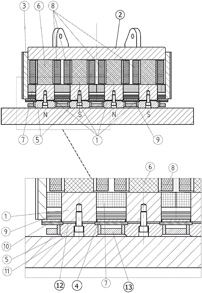
[0017] Referring to these figures, it can be seen that a jack with electro-permanent magnets according to the present invention generally includes an outer support structure, a plurality of electro-permanent magnets and a regulating circuit.

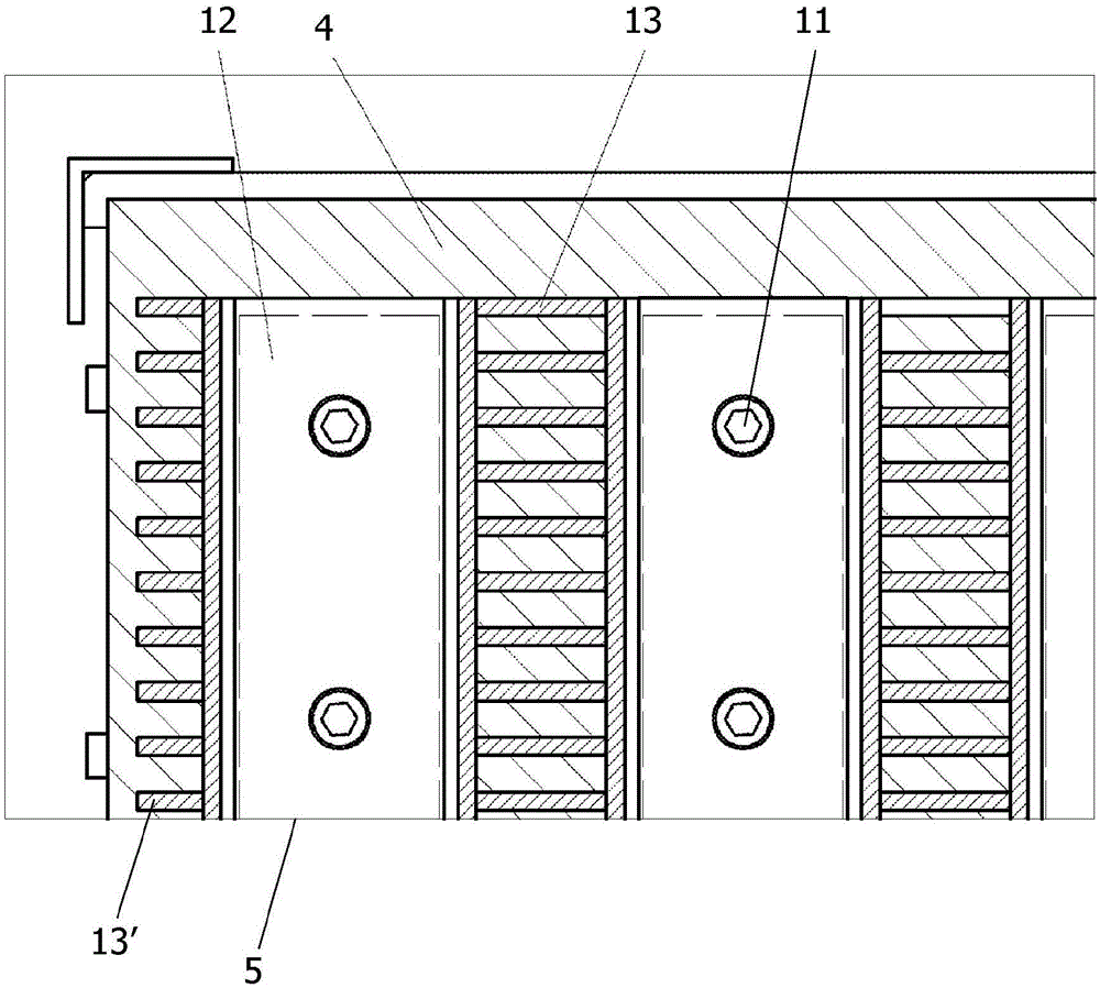
[0018] The support structure comprises a top cover 2 provided with a coupling for connection to a lifting device such as a crane, two peripheral walls 3, and a heat shield 9 provided to protect the magnets from radiation by the hot ferromagnetic material to be lifted. Thermal bottom closure plate 10 . Same as the circuit pole 1 and pole piece 5, said structure is obviously made of high magnetic permeability material (usually mild steel) to minimize the reluctance of the magnetic circuit, the pole piece 5 for contacting the load to be lifted is in A closure plate 10 protrudes below and is fixed to pole 1 by screws 11 .

[0019] Each electro-permanent magnet comprises a reversible magnet 6 arranged on top of a pole 1 in contact with it an...


PUM

PropertyMeasurementUnit
heightaaaaaaaaaa
widthaaaaaaaaaa
heightaaaaaaaaaa

Abstract

A lifter with electro-permanent magnets comprises an external bearing structure (2, 3) closed at the bottom by a plate (10), provided with a heat shield (9), and pole pieces (5) secured under the respective poles (1) and protruding from said bottom plate (10), each of the electro-permanent magnets being composed of a reversible magnet (6) arranged on top of one of said poles (1), of a fixed polarization magnet (7) formed by a plurality of blocks placed along the lateral faces of the pole (1) and of a coil (8) arranged around the reversible magnet (6) to cause the reversal of the polarization of the latter by means of an electrical pulse, an airtight air gap (12) between 1 and 4 mm high being formed between each pole piece (5) and the respective pole (1) through the interposition of a plate (4) of thermal insulation material that resists high temperatures provided at each pole (1) with a rectangular window slightly smaller in size than the pole itself, the top sides of the pole pieces (5) and / or the bottom sides of the poles (1) being provided with peripheral recesses suitable to act as seats for the positioning of said plate (4).

Description

technical field [0001] The present invention relates to magnetic jacks, and more particularly to a jack with electro-permanent magnets capable of safely operating ferromagnetic materials at temperatures as high as 600°C-700°C for long periods of time, such as billets, steel ingots, Slabs and similar rolled steel products. Background technique [0002] It is known that magnetic jacks are divided into three categories according to the type of magnet used, namely permanent magnet, electromagnet and electro-permanent magnet, each type of magnet having its own advantages and disadvantages. [0003] The advantages of a jack with permanent magnets are that the power consumption is practically negligible and that the generated magnetic force is reliably constant and independent of an external power supply. On the other hand, magnetic force cannot be added even if needed, and magnets are extremely bulky for lifting heavy objects. Furthermore, load release requires the application o...

Claims


Application Information

Patent Timeline
Patent Type & Authority Applications(China)
IPC IPC(8): B66C1/06B66C1/08H01F7/02
CPCB66C1/04B66C1/06B66C2700/087
Inventor 达尼洛·莫尔特尼
Owner SGM MAGNETICS SPA
Why Eureka
Try Eureka