Bypass valve arrangement and exhaust system

A technology of exhaust system and bypass valve, which is applied in the direction of valve device, exhaust treatment, noise reduction device, etc., and can solve the problem of a large amount of space in the pipeline

Active Publication Date: 2016-07-06
WARTSILA FINLAND OY
View PDF5 Cites 0 Cited by
  • Summary
  • Abstract
  • Description
  • Claims
  • Application Information

AI Technical Summary

Problems solved by technology

Each bypass valve requires its own actuator and the piping requires a lot of space, which is problematic especially in marine engines

Method used


Image

  • Bypass valve arrangement and exhaust system
  • Bypass valve arrangement and exhaust system
  • Bypass valve arrangement and exhaust system

Examples


Embodiment Construction

[0018] Embodiments of the present invention will now be described in more detail with reference to the accompanying drawings.

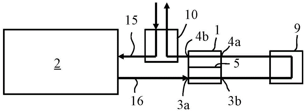
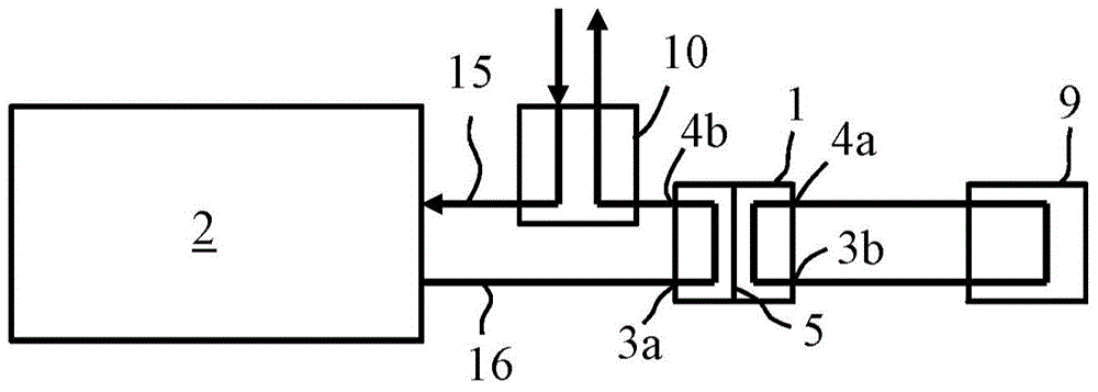
[0019] figure 1 Internal combustion engine 2 is shown schematically. The engine 2 is a large internal combustion engine 2, such as an engine used as a main or auxiliary engine of a ship or for producing electricity in a power plant. The exhaust system of the engine 2 comprises an exhaust manifold 16 and a turbocharger 10 for supercharging the intake air of the engine 2 and directing this air into the cylinders of the engine 2 through an intake manifold 15 . The exhaust system is also provided with a catalyst device 9 which may, for example, be an oxidation catalyst reducing the hydrocarbon and CO emissions of the engine 2 . Oxidation catalysts require relatively high exhaust gas temperatures, and the oxidation catalyst 9 of the engine 2 is therefore located upstream of the turbocharger 10 in the exhaust system. Under some operating conditions of th...


PUM


Abstract

A bypass valve arrangement (1) for an exhaust system of an internal combustion engine (2) comprises a valve (5) and a first inlet (3a), a second inlet (4a), a first outlet (3b) and a second outlet (4b) catheter. In the first position of the valve (5), fluid is allowed to flow from the first inlet (3a) to the first outlet (3b) and from the second inlet (4a) to the second outlet (4b), and prevent fluid from flowing from the first inlet (3a) to the second outlet (4b) and from the second inlet (4a) to the first outlet (3b). In the second position, fluid flow from the first inlet (3a) to the second outlet (4b) and from the second inlet (4a) to the first outlet (3b) is allowed and blocked Fluid flows from the first inlet (3a) to the first outlet (3b) and from the second inlet (4a) to the second outlet (4b). The invention also relates to an exhaust system.

Description

technical field [0001] The invention relates to a bypass valve arrangement for an exhaust system of an internal combustion engine. The invention also relates to an exhaust system for an internal combustion engine. Background technique [0002] In order to meet emission restrictions, many internal combustion engines are provided with catalytic devices, such as oxidation catalysts and / or catalytic converters for selective catalytic reduction (SCR). Under some operating conditions, it may be necessary to bypass the catalyst unit. This may be the case, for example, when a dual fuel engine is operated on liquid fuel containing sulphur, which would deactivate the oxidation catalyst. Engines therefore often include a bypass line for leading the exhaust gas through the oxidation catalyst or catalytic converter for SCR. At least two valves are required to direct the exhaust gas into the bypass pipe and block the connection to the catalyst device. Each bypass valve requires its ow...

Claims


Application Information

Patent Timeline
Patent Type & Authority Patents(China)
IPC IPC(8): F01N13/18F01N13/00
CPCF01N3/103F01N3/2053F01N13/00F01N13/1861F02B37/02F01N2240/36F01N2390/00F01N2410/00Y02T10/12F01N13/1805F16K1/22
Inventor K·伦丁
Owner WARTSILA FINLAND OY
Why Eureka
Try Eureka