Monoflange valve

a technology of monoflanges and valve bodies, applied in the field of monoflange valves, can solve the problems of processing fluids clogging in the valve body, limiting the space available for radiographic examination, and reducing the fluid flow characteristics of known monoflange designs, etc., to achieve the effect of increasing the length and tortuosity of the flow path, limiting the space available for radiographic examination, and increasing the length of the flow path

Active Publication Date: 2018-10-09
PARKER INTANGIBLES LLC
View PDF3 Cites 0 Cited by
  • Summary
  • Abstract
  • Description
  • Claims
  • Application Information

AI Technical Summary

Benefits of technology

[0005]Known monoflange valves of the type described above typically have a configuration in which the valve assemblies are welded at locations that are too close to the valve body to allow for automatic weldment processes to generate consistent and stable welds. The placement of such welded joint connections close to the valve body also limits the space available for radiographic examination of the weld. Known monoflange valve designs also typically locate the valve seats that cooperate with the valve assemblies close to the outer periphery of the valve body, which increases the length and tortuosity of the flow path through the valve body. This reduces the fluid flow characteristics of known monoflange designs, and potentially causes the processing fluids to clog in the valve body.
[0006]According to one aspect, the present invention provides a monoflange valve assembly having at least one centrally located valve seat that cooperates with at least one valve member to open or close a fluid flow path through the valve body. More particularly, the centrally located valve seat may be located close to an axial inlet passage to reduce the length and tortuosity of the flow path through the valve body, which may enhance fluid flow through the valve body.
[0008]According to another aspect, the present invention provides a monoflange valve assembly having a main monoflange body with one or more projections extending radially outwardly from the main body. One or more valve assemblies may be welded to the respective projections at locations spaced radially outwardly from the main valve body. Locating the weldment of the valve assemblies to the projections away from the valve body in this way may facilitate welding and / or inspection of the weldment at the attachment interface. More particularly, such a configuration may provide sufficient spacing for automatic weldment processes to generate a consistent and stable weld (e.g., 100% full weld penetration), as well as enable sufficient spacing from the main monoflange body for improved visual and / or radiographic inspection of the weld (e.g., 100% inspection of the weld area).
[0009]In exemplary embodiments, the one or more valve assemblies that are welded to the respective projections may include one or more sealing members, such as a bellows and a bonnet. The one or more sealing members may be respectively sealingly attached to each other, to other parts of the valve assembly, and to the valve body projection so as to reduce or eliminate leakage of the processing fluid out of the valve body.
[0012]According to another aspect of the invention, a monoflange valve assembly includes a monoflange body having a main body portion, the main body portion having an axial fluid passage for communication with a fluid stream; a projection extending radially outwardly from the main body portion, the projection having an internal bore that extends radially inwardly through the projection and connects with the axial fluid passage of the main body portion; and a valve assembly having an attachment body welded to the projection at a location spaced radially outwardly from the main body portion, thereby facilitating welding and / or inspection of the weldment.

Problems solved by technology

The placement of such welded joint connections close to the valve body also limits the space available for radiographic examination of the weld.
This reduces the fluid flow characteristics of known monoflange designs, and potentially causes the processing fluids to clog in the valve body.

Method used


Image

  • Monoflange valve
  • Monoflange valve
  • Monoflange valve

Examples


Embodiment Construction

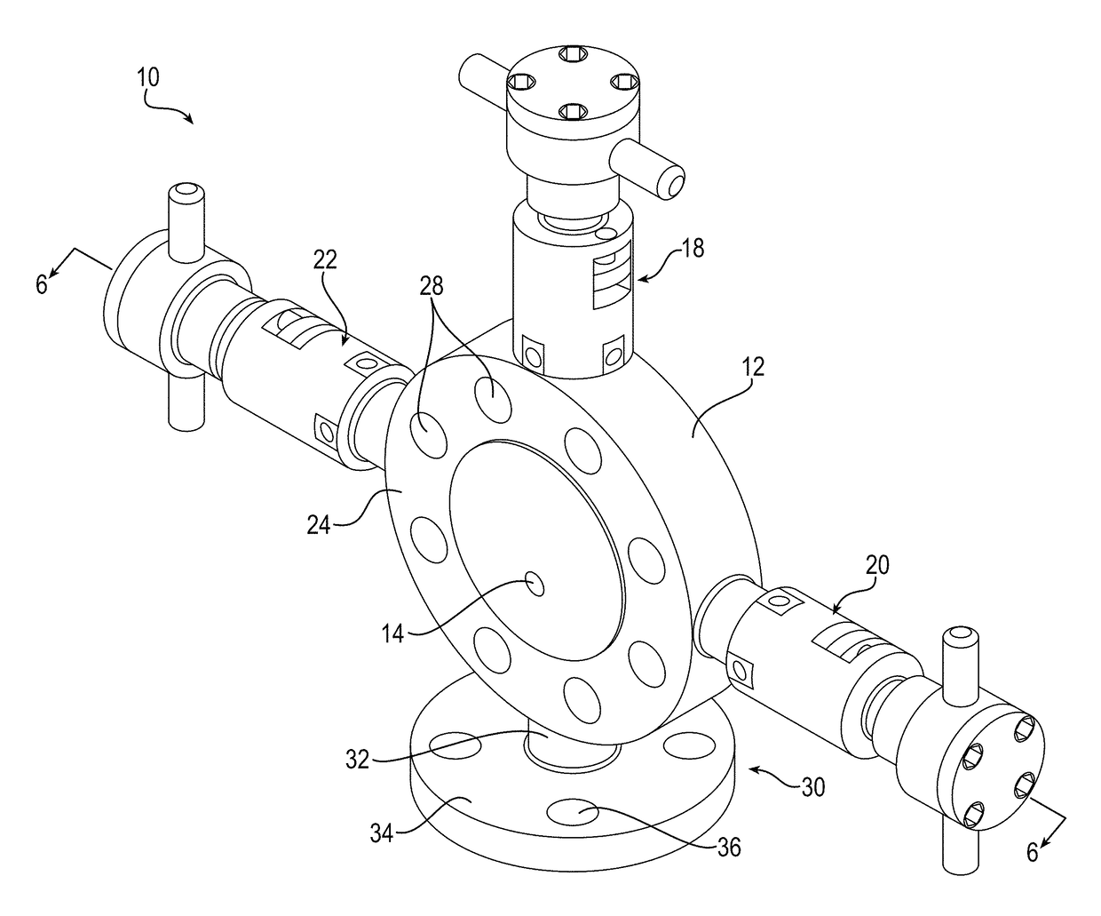
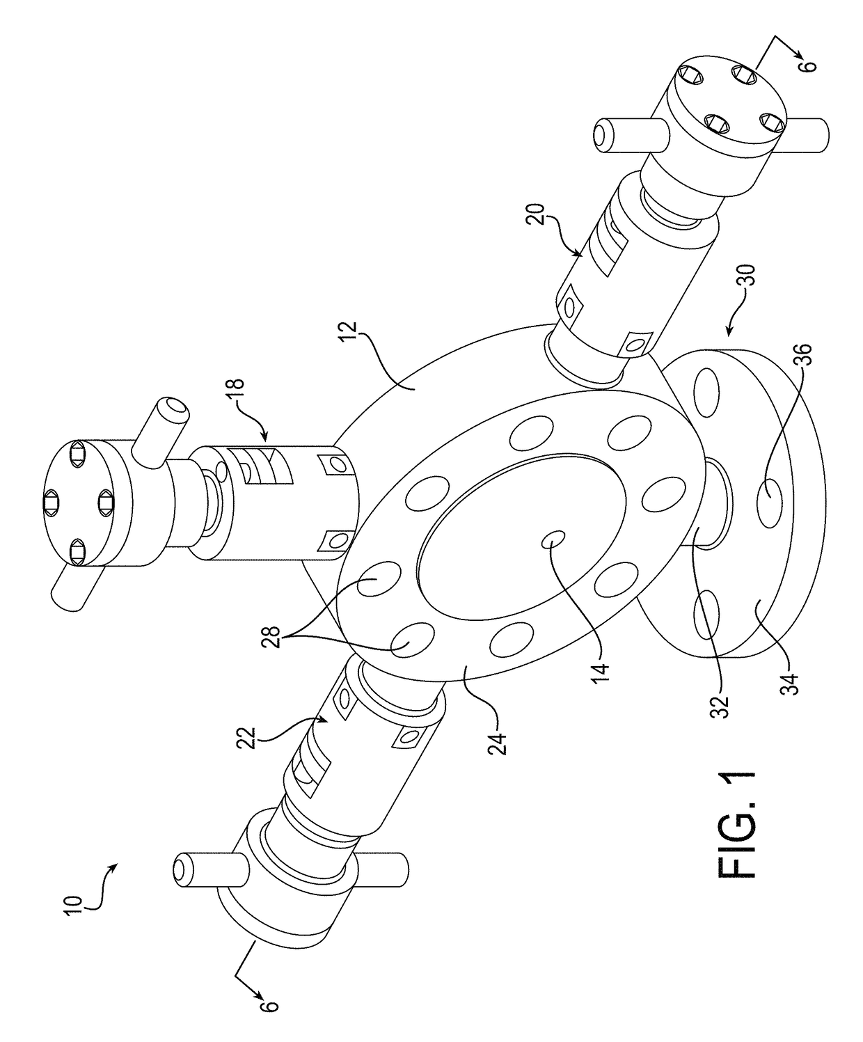
[0030]The principles of the present invention have particular application to monoflange valve assemblies for use with severe service media, such as Phosgene (COCl2), Chlorine (Cl), Anhydrous Ammonia (NH3), Cyanide (CN), and / or other severe media, including those from Category M of ASME B31.3, and thus will be described below chiefly in this context. It is also understood, however, that principles of this invention may be applicable for use in other applications, including non-severe media applications, where it is desirable to enhance fluid flow characteristics during use, or to facilitate welding and / or inspection of the monoflange valve assembly before use in such applications.

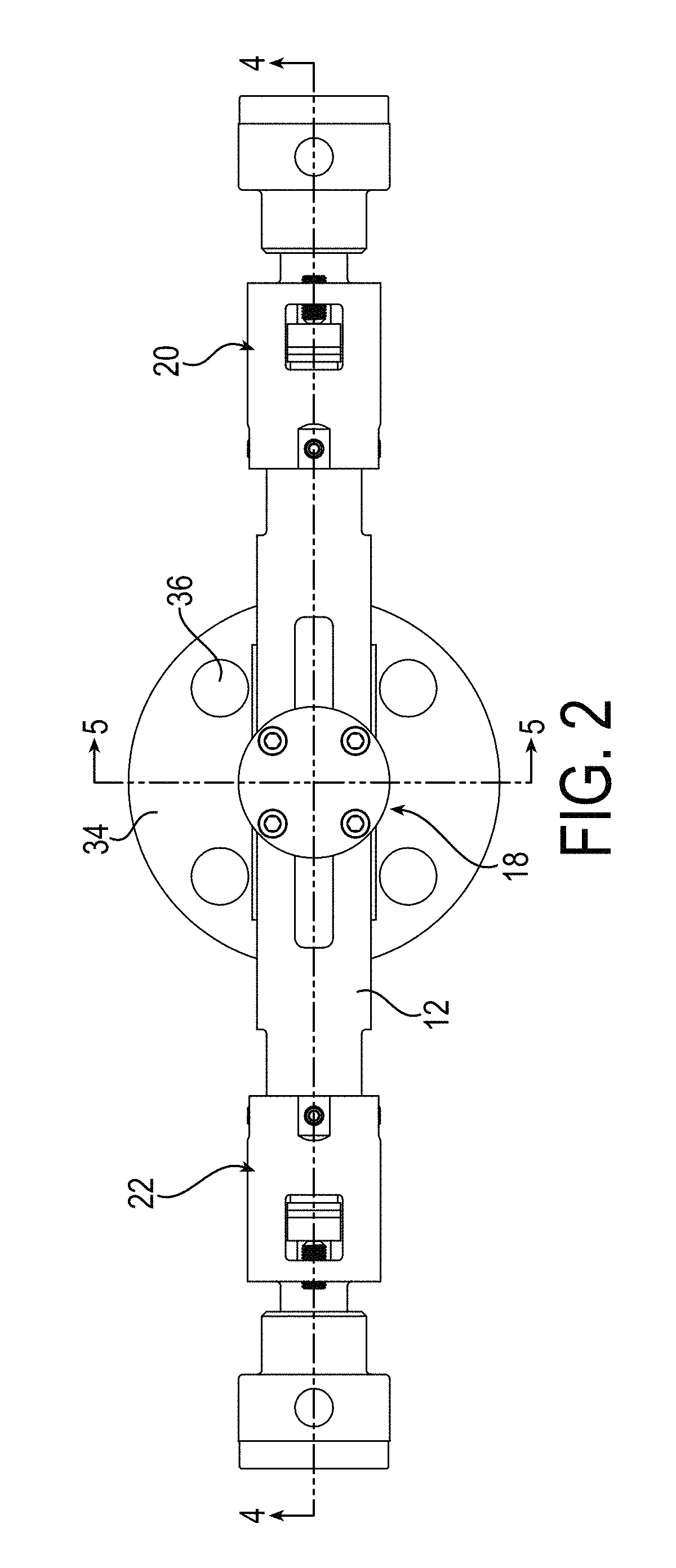
[0031]Turning to FIGS. 1-3, an exemplary monoflange valve assembly 10 is shown. The monoflange valve assembly 10 includes a main body portion 12 having an axial inlet fluid passage 14 (shown in FIG. 1), an outlet fluid passage 16 (shown in FIG. 3), and one or more valve assemblies 18, 20, 22 for enabling or ...


PUM


Abstract

A monoflange valve including a valve body having an inlet, an outlet, and an internal bore, and a valve assembly having a valve member disposed in the internal bore for cooperating with a valve seat to open or close a flow path through the valve body. The valve seat may be disposed in the internal bore at a central region of the monoflange body proximal the inlet for enhancing fluid flow through the monoflange body. One or more valve assemblies may be provided, each having a corresponding valve seat that may be located at the central region proximal the inlet passage. One or more projections may extend radially outwardly from the valve body, and the valve assemblies may have a sealing member welded to the corresponding projection at a location spaced radially outwardly from the valve body for facilitating welding and / or inspection of the weldment.

Description

RELATED APPLICATIONS[0001]This application claims the benefit of U.S. Provisional Application No. 62 / 237,902 filed Oct. 6, 2015, which is hereby incorporated herein by reference in its entirety.FIELD OF INVENTION[0002]The present invention relates generally to a monoflange valve, and more particularly to a monoflange valve assembly for use with processing fluids including severe service media.BACKGROUND[0003]Monoflange valves are typically used for pressure instrumentation take-off points, isolation, sampling, injection, venting, or purging of processing fluids. These monoflange valves typically have a valve body with a flange interface for mounting directly onto a flanged connection located upstream or downstream of processing equipment. Known monoflange valves typically have an axial inlet passage and an outlet passage for communicating the processing fluid from a main fluid conduit to a pressure gauge or other instrumentation. In addition, known monoflange valves typically includ...

Claims


Application Information

Patent Timeline
Patent Type & Authority Patents(United States)
IPC IPC(8): F16K11/20F16K17/02F16K11/22F16K17/04
CPCF16K11/20F16K11/22F16K17/0473F16K17/02Y10T137/87917
Inventor CHENG, MIKE KONGSUN, XIAOPENG
Owner PARKER INTANGIBLES LLC
Why Eureka
Try Eureka