Installation of a receiver as part of an x-ray tube housing

a receiver and tube housing technology, applied in the field of x-ray receivers, can solve the problems of limiting the placement of the sensor in the mouth, and extra wires being annoying to the patient and clinician

Active Publication Date: 2009-06-23
SIRONA DENTAL
View PDF37 Cites 5 Cited by
  • Summary
  • Abstract
  • Description
  • Claims
  • Application Information

AI Technical Summary

Benefits of technology

[0015]It also is an object of this invention to provide a wireless receiver and its related circuitry in a location where problems caused by practical factors such as the limited distance from the transmitter to the receiver, the limited space available for the transmission circuitry within the wireless electronic sensor, and the limited power requirements, can be overcome. One advantage of the invention is that it allows medical and dental imaging detectors to more reliably transmit digital data to a computer or image processing unit.
[0016]It is also an object of this invention to provide an x-ray system for use with wireless or wired electronic sensors.
[0017]In accordance with the teachings of the present invention, these and other objects may be accomplished by the present invention, which in one embodiment is a wireless receiver conveniently mounted within a collimator or the housing of an x-ray tube for receiving x-ray imaging data to be transmitted to an image processing unit.
[0018]In another embodiment a wireless receiver comprises an antenna which may be slid into the cavity of the collimator or x-ray tube housing. The wireless receiver may be affixed to the inner diameter of the collimator or x-ray tube housing with adhesive, tape, or a clip. The receiver electronics may be housed inside the cavity or alternatively outside the housing in closer proximity to the image processing unit.
[0019]In another embodiment, a coil is provided in the collimator, and a wire transmits the information to a control box, where the x-ray tube settings are typically located. Interface electronics (such as those which utilize the Universal Serial Bus or USB of a computer) for the wireless sensor are located in the control box. The control box would preferably have a USB port through which the information could be passed directly to a computer.
[0020]Communication between the control box and the computer may be effected by way of a commonly available and accessible digital port such as, but not limited to, the USB. The USB is a serial 12 megabit per second (Mbps) channel that can be used for peripherals. The USB is a token-based bus; that is, the USB host controller broadcasts tokens on the bus and a device that detects a match on the address in the token responds by either accepting or sending data to the host. The host also manages USB bus power by supporting suspend / resume operations. The USB is advantageous in that it does not require the use of specially designed hardware inside the computer; once the appropriate software has been installed, a peripheral can be plugged into the USB port.

Problems solved by technology

For example, extra wires can be annoying to the patient and clinician.
In addition, in certain diagnostic procedures, the sensor wires may be cumbersome and could limit placement of the sensor with respect to the x-ray tube and computer.
In digital dental radiography, such wires can limit sensor placement in the mouth.
Furthermore, mechanical failure of the wire due to strain is a common failure mechanism.
A wire may also create a trip hazard.
Thus, as discussed above, the image data is often conveyed from the detector using a long flexible cable, and in certain applications this cable can be inconvenient for the patient and the operator as it may present various electrical and mechanical constraints.
While Spahn's design may offer some measure of flexibility, it suffers from a number of drawbacks in that it does not address certain technically challenging aspects of achieving its end.
In practice, the distance from the transmitter to the receiver must typically be quite limited.
This is because the waveform usually carries large volumes of data and may be blocked by obstructions such as medical equipment or the patient's anatomy.
In yet other scenarios, such as in intra-oral dental imaging, there may be a limited amount of space available for the transmission circuitry within the sensor, and thus a less stable and lower power voltage controlled oscillator may be used.
The overall power available to transmit a pulse may also be limited.
And Federal regulatory bodies and hospitals commonly limit the amount of transmitted power that a design may utilize.
Moreover, it is often difficult to find a convenient and workable location for the receiver.
Medical and dental offices typically contain furniture, equipment, and cabling that together limit the practical location for such a device.
Given factors such as these, finding an appropriate location for the receiver and its related circuitry is a formidable task.
Although prior art techniques are generally good for their intended purposes, they do not sufficiently address problems including those explained above.

Method used


Image

  • Installation of a receiver as part of an x-ray tube housing
  • Installation of a receiver as part of an x-ray tube housing
  • Installation of a receiver as part of an x-ray tube housing

Examples


Embodiment Construction

[0041]The invention will next be described in connection with certain exemplary embodiments; however, it should be clear to those skilled in the art that various modifications, additions, and subtractions can be made without departing from the spirit or scope of the claims.

[0042]The present invention is directed to x-ray systems, e.g., for use in medical or dental applications. The present invention may be used with charge-coupled devices (CCDs), active pixel sensor (APS) arrays, or any other suitable type of receptor.

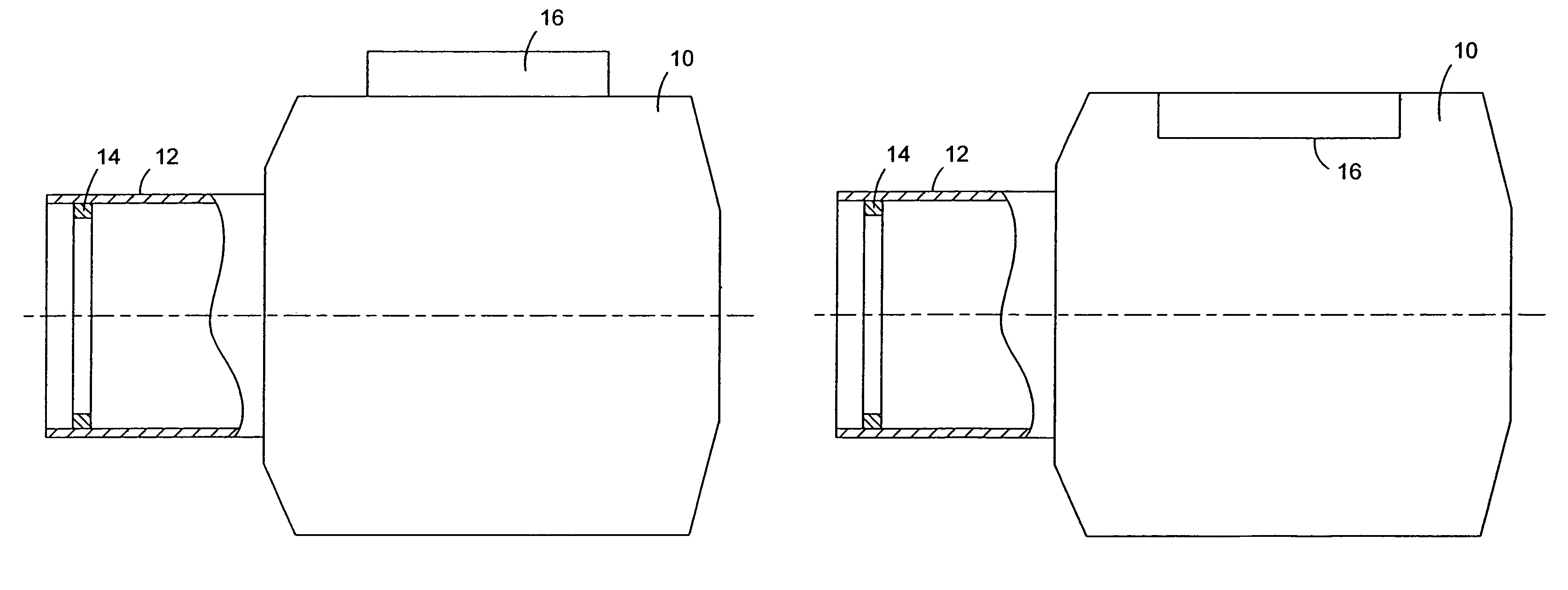
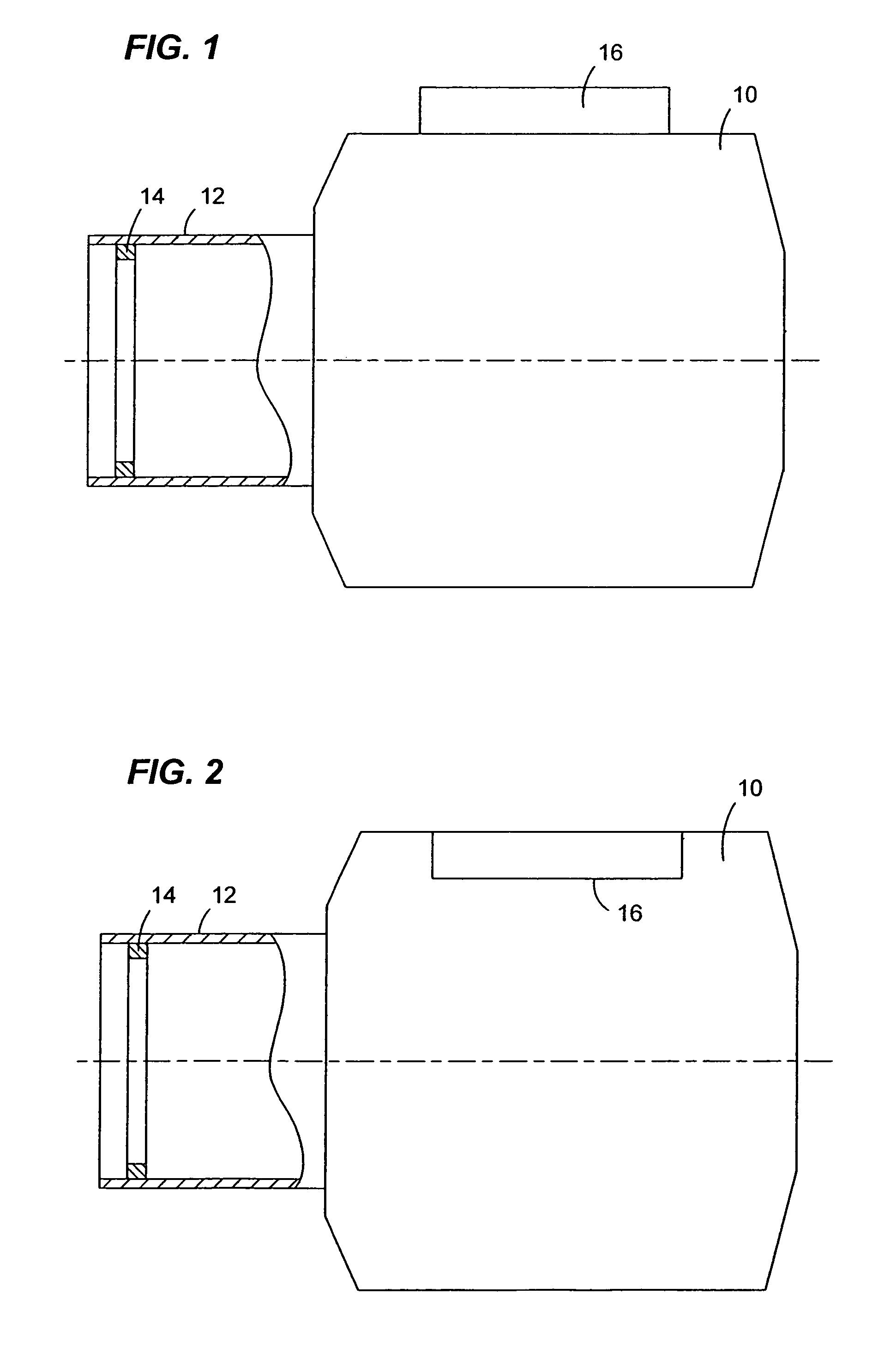
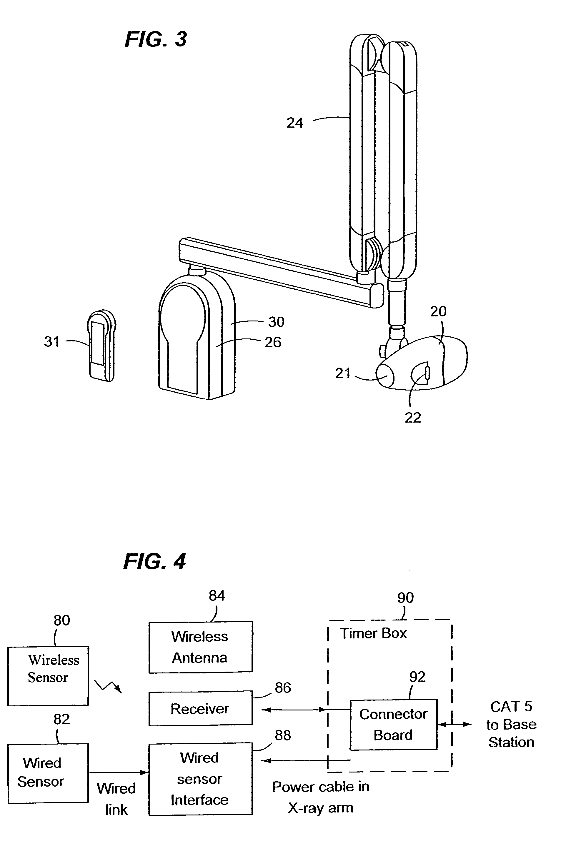
[0043]As explained previously, one of the challenges related to wireless sensors has been to identify a practical and convenient location for the radiofrequency (RF) receiver and its related circuitry. The antenna should preferably be within reasonably close proximity to the transmitter that is typically housed within the sensor. On one hand, medical and dental offices typically contain furniture, equipment, and cabling that together limit the practical location for su...


PUM


Abstract

An x-ray system comprises an x-ray tube, covered by a housing, which emits x-rays therefrom, and a receiver mounted within the x-ray tube housing. An electronic sensor receives the emitted x-rays, converts the received x-rays into electrical image data signals, and transmits the electrical image data signals to the receiver. An image processing unit processes the electrical image data signals received from the receiver.

Description

BACKGROUND OF THE INVENTION[0001]1. Field of the Invention[0002]This invention relates generally to the field of x-ray systems, and more particularly to an x-ray receiver for medical and dental applications that is mountable within an x-ray tube housing.[0003]2. Related Art[0004]X-ray receptors have long been employed in the fields of medicine and dentistry to capture images representing the human anatomy. These images are often used by physicians and dentists to aid in the diagnosis and treatment of conditions and disease. In the case of dentists and oral surgeons, images of a patient's teeth, mouth, and gums are used to aid in diagnosis and treatment. The most conventional technique is to use radiographic film as the imaging receptor. However, solid-state sensors which convert x-rays into an electrical signal have increasingly begun to be used in place of photographic film.[0005]Such filmless radiography systems offer many advantages over traditional film-based radiography. For ex...

Claims


Application Information

Patent Timeline
Patent Type & Authority Patents(United States)
IPC IPC(8): H05G1/08H05G1/64A61B6/14
CPCA61B6/14A61B6/4233A61B6/563A61B6/548A61B6/145
Inventor SCHICK, DAVID B.BRATSLAVSKY, AARONMANDELKERN, STANMICHAELI, DANIELSTONE, MICHAEL C.
Owner SIRONA DENTAL
Why Eureka
Try Eureka